


1. Purpose and Objectives
1.1 General
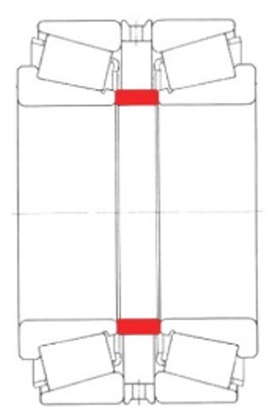
Figure 1
In practice, there are several methods for pairing and preloading tapered roller bearings: back-to-back (O-arrangement, DB), face-to-face (X-arrangement, DF), tandem (to increase axial load capacity), as well as clearance-matched, rigidly preloaded, or spring-preloaded arrangements. For factory-matched duplex sets, preload or axial internal clearance is predefined by the supplied spacer rings.
Pairing non-factory-matched bearings, by contrast, requires additional effort: preliminary measurement of the relevant axial as-measured dimensions of the bearings and, where applicable, the housing; definition of the target axial clearance; and for an O-arrangement in addition to an outer spacer ring, the manufacture of an inner spacer ring (Figure 1) ground to the required accuracy to meet the service conditions.
1.2 Preload principle
If a specifically preloaded tapered-roller bearing pair is to be supported in a rigid back-to-back (O) arrangement via the housing, the housing width (HW) must also be determined to calculate the effective spacer length (see Figure 2). The illustration reflects nominal geometric distances only and does not account for physical effects such as thermal expansion or fit-induced interference.
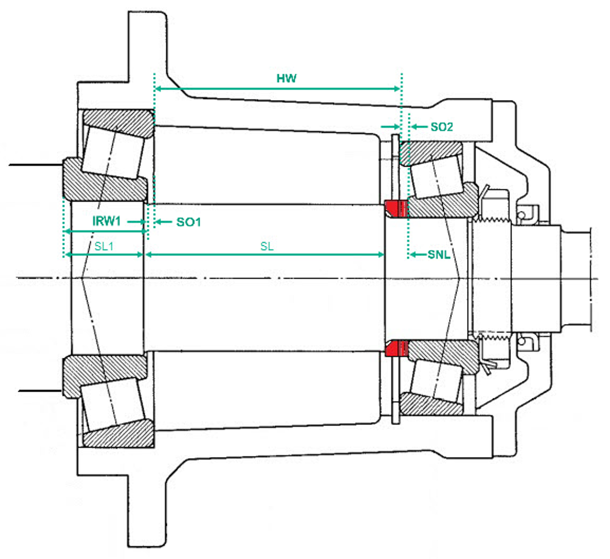
Figure 2
The measured end-face standouts (Fig. 3), together with the housing width (HW), are used to determine the internal axial spacing between the two bearings.
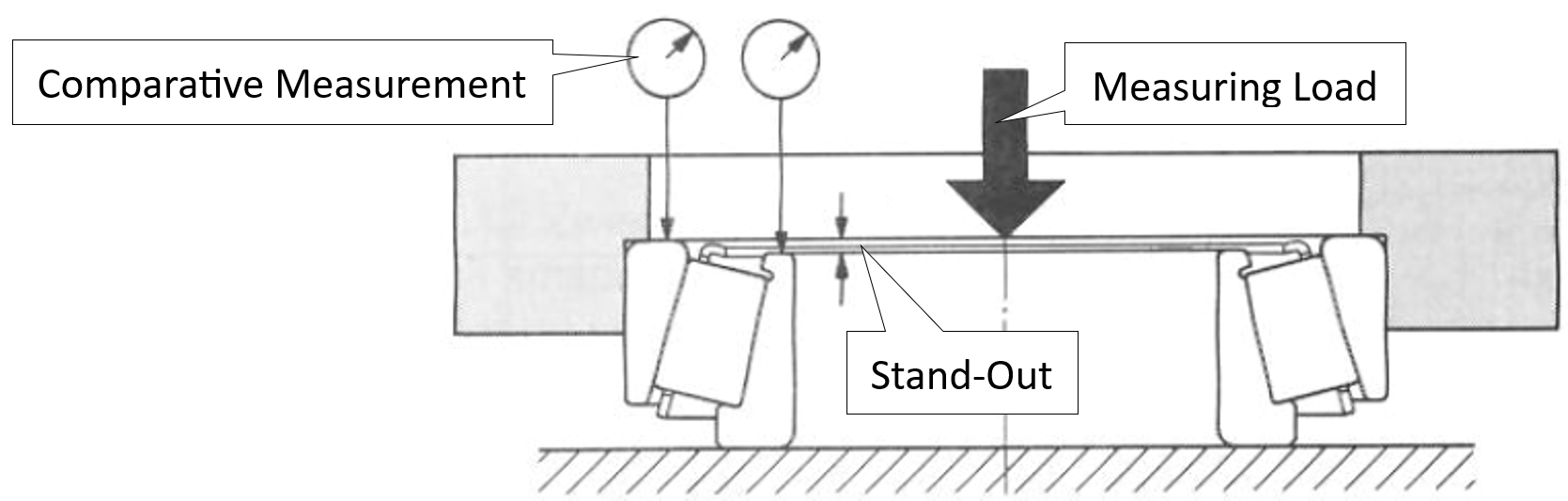
Figure 3
This also allows the spacer nominal length (SNL) to be determined as: SNL = (HW) + Stand-Outs (SO1 & 2) + Inner Ring Width 1 (IRW1) – Shaft Segment Length’s (SL1 & SL):
SNL = HW + SO1 + SO2 + IRW – (SL1+ SL)
The axial shortening to be specified for the spacer corresponds – after accounting for dynamic, thermal, and elastic effects – to the preload displacement of the tapered-roller bearing pair. These effects can be computed efficiently with MESYS.
1.3 Application Example
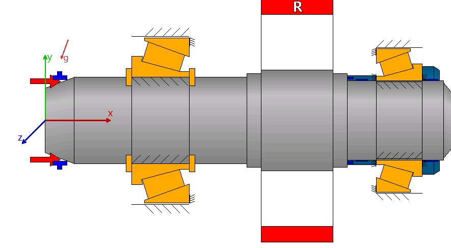
Figure 4
This document explains the design of a rigidly preloaded tapered-roller bearing pair in O-arrangement (back-to-back) for supporting a gearbox output shaft in a marine application. The objective is to use the MESYS shaft calculation to directly determine the required bearing preload while accounting for all measurable influences from a defined operating condition.
A suitable bearing preload is defined by specifying the axial preload displacement. It is achieved by the inner spacer and by the necessary clamping force generated by the shaft nut.
1.4 Framework and Application-Specific Aspects
The most likely load cases – propeller thrust forward (ahead) and reverse (astern) – are considered. The forces from the helical gear mesh enter the load model of the output shaft and bearing pair as tangential, radial, and axial components.
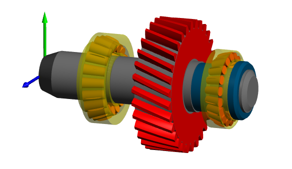
Figure 5
Environmental conditions: oil lubrication, temperature differentials between shaft and housing, assembly and fit interferences (IR/OR) are taken into account.
Because forward thrust predominates over time, unequal bearing sizes are used.
1.5 Design objectives and verification strategy
The design shall maintain a minimum bearing load in every operating state, insofar as other boundary conditions are not violated. Slip states – especially under strong load reversals – and the resulting roller lift-off are to be excluded. The higher temperature rise due to the increased base load from preload is acceptable under oil lubrication.
Service life is verified using a transparent duty cycle. The four operating states STOP, IDLE, AHEAD, ASTERN are each considered at a fixed gear ratio, weighted with hypothetical time shares, and condensed to an equivalent bearing load. On this basis, either an overhaul interval of 7 years or a modified reference life of at least 11’200 h is verified.
The correct nut setting force is derived from the sum of force components: the force required to displace the rings against interference with shaft or housing, the resulting preload in the bearing pair, and an additional clamping force of the nut to compensate dynamic effects on the assembly. Their sum defines the setting force to be applied; the associated nut tightening torque is not pursued further here.
Robustness of the preload design is demonstrated by parameterizing fit tolerance positions and assumed temperature gradients, and evaluating their influence under a single equivalent load consistent with the duty cycle used for system life.
2. Baseline
2.1 Drive concept
The application under study is the output shaft of a marine gearbox. For forward thrust of 25 kN (ahead) a torque of 2500 Nm is assumed, for reverse thrust (astern) 1500 Nm – in each case at a constant speed of 1600 rpm.
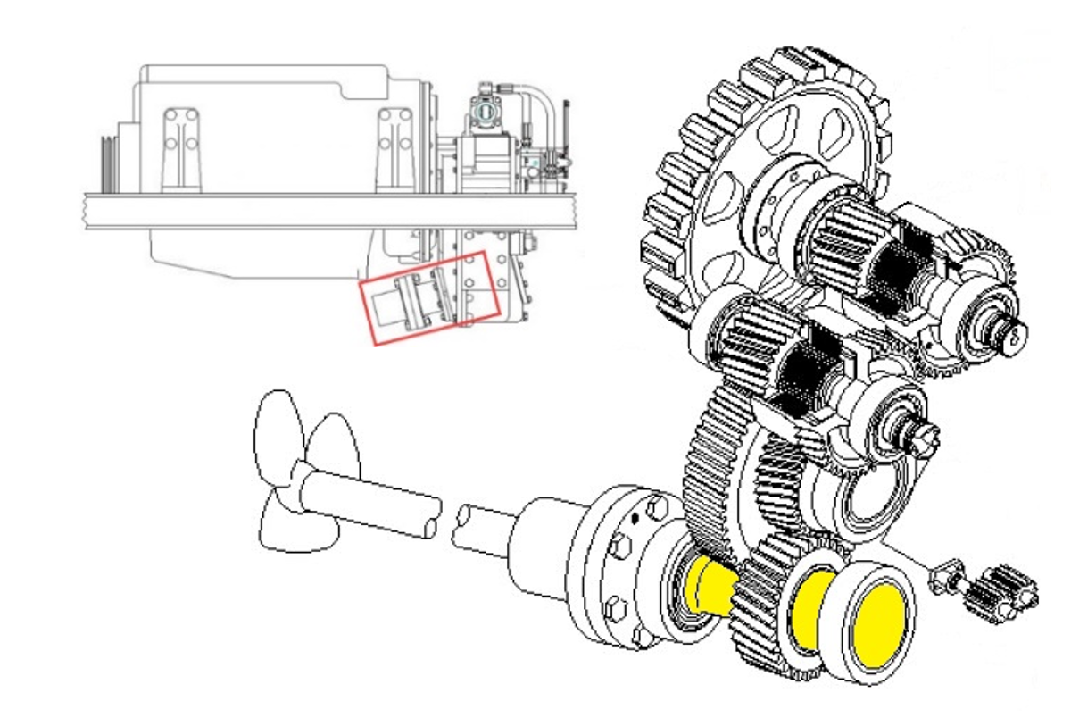
Figure 6
The associated thrust forces are derived without a detailed propeller design using the open-water approach, which uses the dimensionless propeller coefficients KT (thrust) and KQ (torque).
Tprop = KT/KQ * Q/D
With a fixed propeller diameter D and a constant KT/KQ ratio at the operating point, the thrust is proportional to the shaft torque Q. Accordingly, the thrust levels can be derived consistently from the torque values.
2.2 Helical Gear
For power transmission, a helical gear with a helix angle of 20°, with further characteristics as shown in Figure 7, is used:
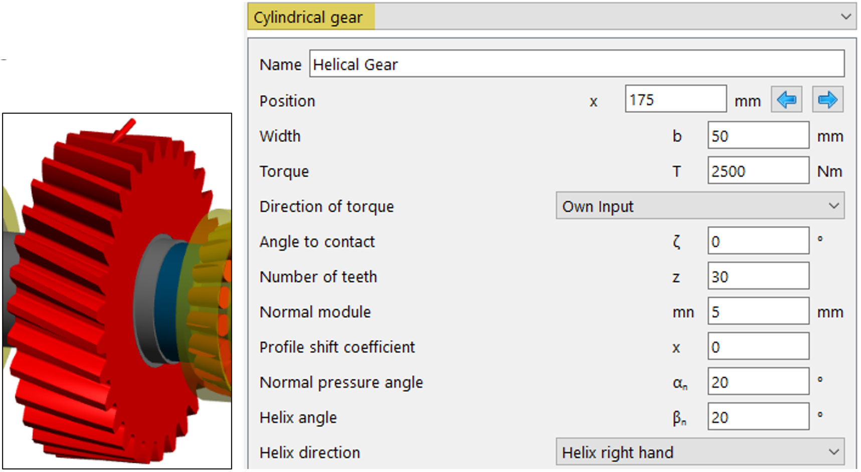
Figure 7
2.3 Bearing arrangement concept
The solid shaft with mounted gear is supported by two tapered roller bearings in a rigidly preloaded back-to-back arrangement.
The following gear and bearing configurations are used:
– Gear with b = 50 mm; z = 30; mn = 5; helix angle βn = 20°
– Outboard: 60 x 115 x 40 with 20° contact angle; C = 156.064 kN, C0 = 211.631 kN
– Inboard: 55 x 100 x 32 with 19.8° contact angle; C = 111.023 kN, C0 = 147.668 kN.
The back-to-back arrangement provides high tilting stiffness and unambiguous axial support in both directions; the larger outboard bearing with a 20° contact angle addresses the dominant ahead thrust. The fixed preload can be set via a defined axial preload displacement (spacer plus nut clamping force) and can be determined in advance by calculation, taking into account fits and temperature differentials.
3. Adjustment parameters
3.1 Minimum load
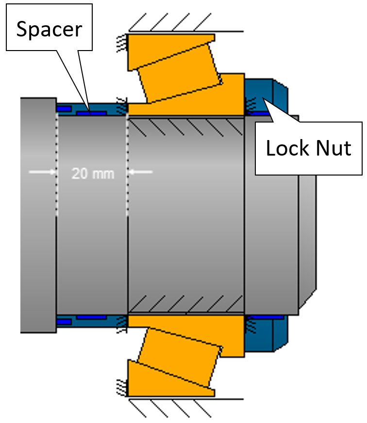
Figure 8
The preload displacement is selected by parameter-varying the spacer length with a nominal 20 mm (Figure 8) so that the minimum roller contact pressure (pmin) remains, as far as feasible, safely above zero even in the critical element of the load spectrum.
3.2 Service Life
A compromise is chosen between minimum load and bearing life, acknowledging that life is coupled to the frictional losses induced by preload.
3.3 Locknut clamping force
The locknut clamping force is determined as the sum of the contributing force components toward the required total clamping force – namely the bearing displacement (assembly) force, the bearing preload force, and a supplementary retaining force – and is set such that the target preload of the bearing set is maintained.
3.4 Tolerance fields
Finally, on the basis of the results of a parameter variation, the behaviour under combinations of the tolerance fields for fits and the corresponding temperature differentials is examined in order to seek confirmation of the selected setting.
4. Method for the determination of target values
4.1 Elastic ring expansion
Under axial preload and with clearance fits, the outer ring can expand radially due to the contact angle, while the inner ring can contract. Both effects reduce the effective operating preload. These effects, together with fit conditions and temperature differentials, are included in the calculation so that the set preload displacement meets the target in operation. Consequently, elastic expansion of the rings is taken into account for both bearings.
4.2. Extended calculation model
Outboard, B1:
The ‘extended calculation model’ (Figure 9) allows elements for axial and radial contacts to be defined. It also allows clearance between the bearing ring and the shaft or the housing to be taken into account.
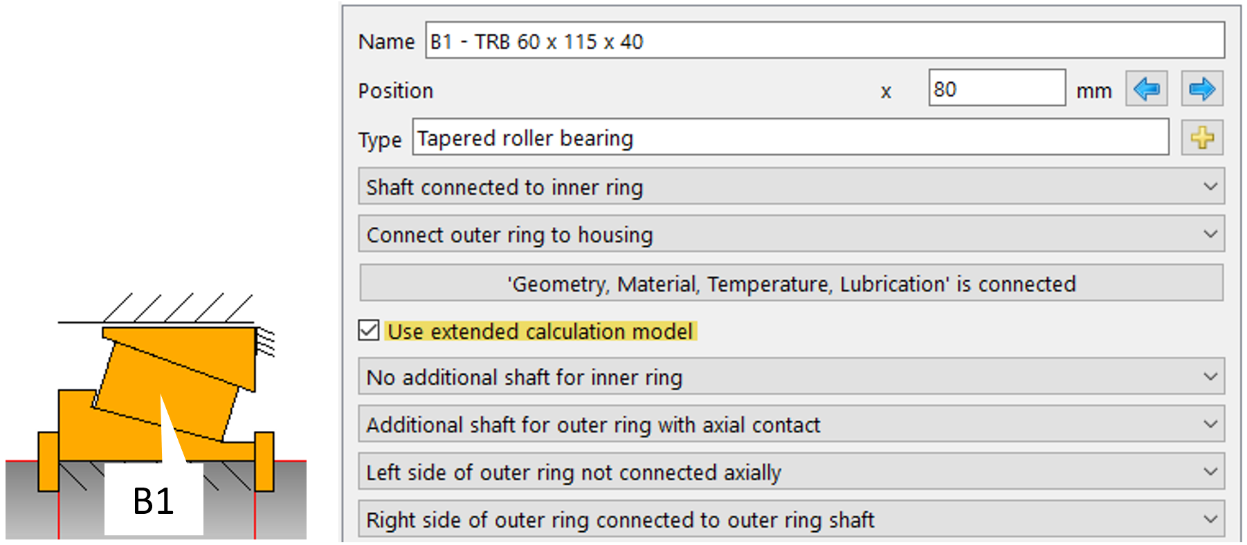
Figure 9
Inboard, B2:
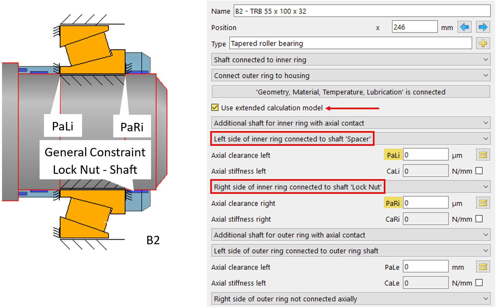
Figure 10
4.3 Load spectrum
A hypothetical load spectrum according to Table 1 is activated:
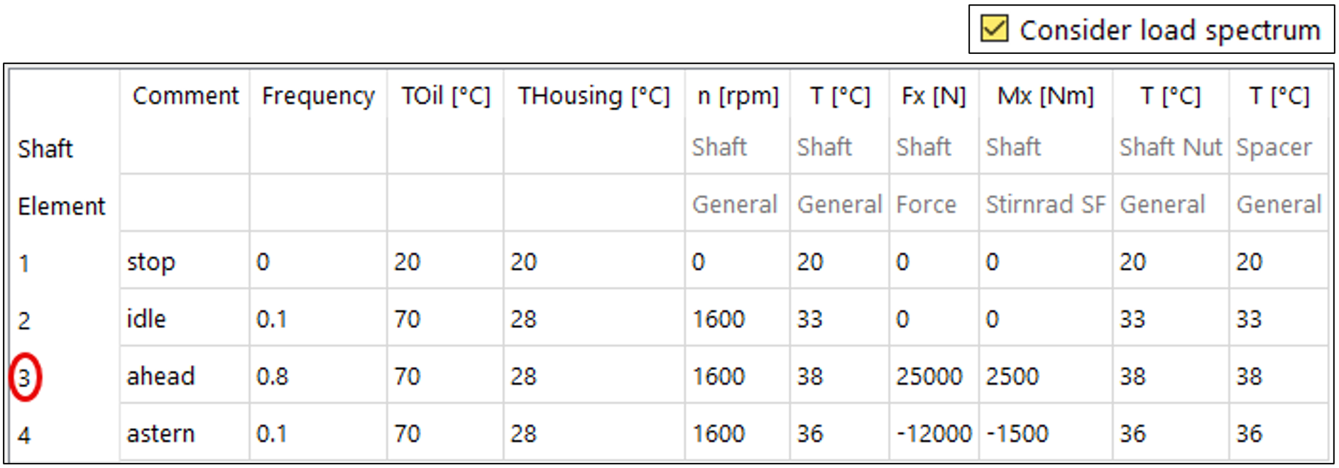
Table 1
Element 3 is designated as the critical condition with regard to bearing loading, tilting (misalignment), and slip, and is therefore the condition of primary interest (Table 1).
4.4 Fits
4.4.1 General

Figure 11
Precision class, fits, surface roughness, and housing diameters according to Figure 11 are taken into account. The settings output in the tolerance report yield, for B2 under load-spectrum element 1, the assembly forces as specified in 4.6.2.
4.4.2 Positions within fit tolerance zone
A preliminary investigation of the ideal preload displacement is, as a practical matter, to be carried out under a tolerance zone representing ‘medium clearance’. In a subsequent step – potentially to safeguard the setting against all conditions – analyses should also be performed for tolerance zones deviating from the mean.
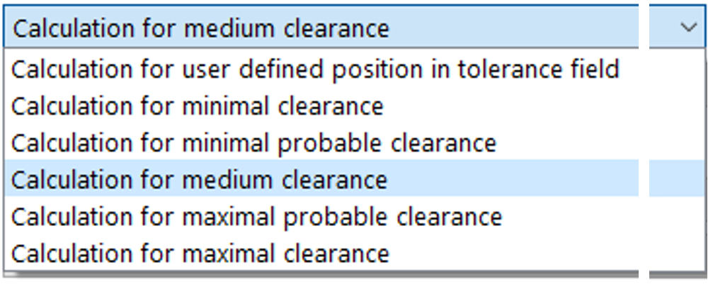
Figure 12
The excerpt from the tolerance report (Table 2) shows, for the cold assembly condition (load-spectrum element 1), the following fit interferences at B1 and B2:

Table 2
4.5 Parameterization of the preload displacement
4.5.1 Parameters
The parameterization of the preload displacement shall be conducted for load-spectrum element 3, as it represents the critical minimum-load case.
The parameter B2-Pa_Li is suitable for representing the variation of the preload displacement by defining axial clearance between the spacer and inner ring B2 (Figure 10). In 20 steps, the shortening of the spacer is to be represented by Pa_Li as the generation of axial clearance between the spacer and bearing inner ring B2. The associated negative interference between the inner ring and the locknut Pa_Ri (Figure 10) shall simultaneously represent a leftward displacement of the inner ring by the parameterized values.
4.5.2 Medium clearance evaluation
It can be assumed that an increase in preload also entails an increase in the temperatures of the shaft, spacer, and locknut (Figure 13):
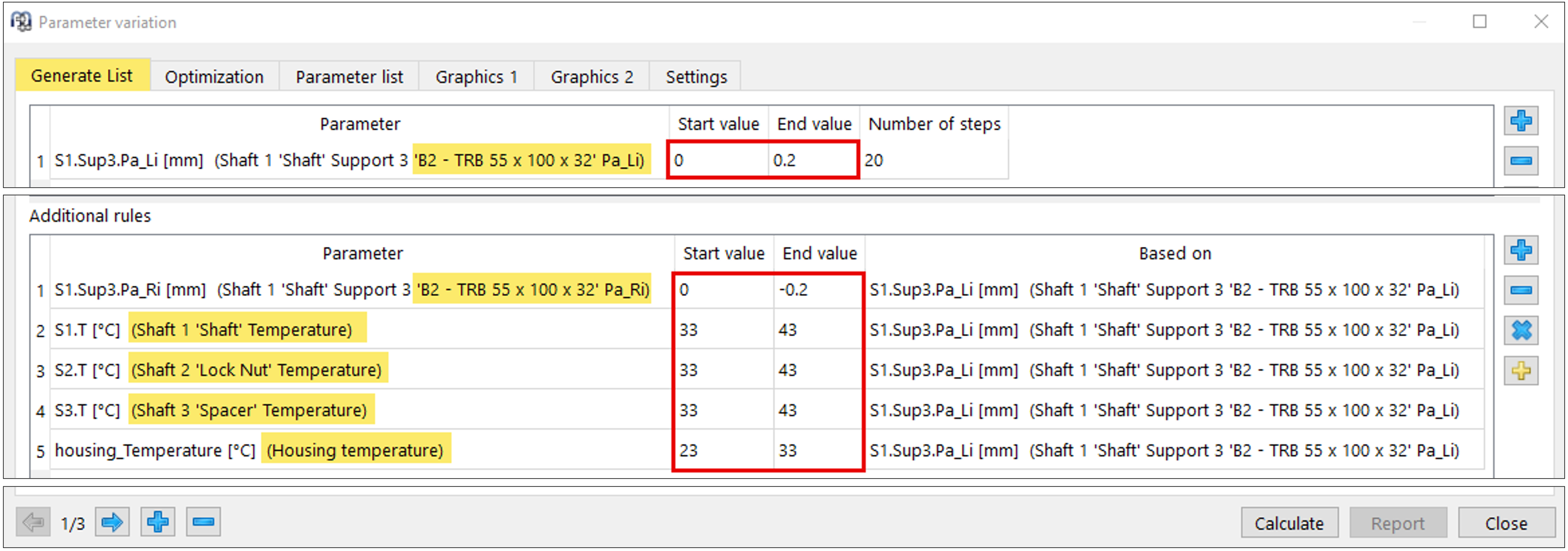
Figure 13
In practice, the temperatures assumed here are often only hypothetical to empirical in character, since corresponding measurements are typically technically or financially challenging.
Parameterization with fit interferences according to the ‘mean value’ – i.e., ‘Calculation for medium clearance’ at both bearings (Figure 12) – yields the following curves for contact pressures and modified reference life under load-spectrum element 3 (Figure 14):

Figure 14
A preload displacement of 100 µm appears to be a practical setting for the critical B2.pmin case: it yields a minimum roller contact pressure of round about 460 MPa – i.e., pmin remains safely > 0 – and delivers a service life above the required value, as shown in the parameter list above:
With the resulting modified reference life, the first two targets set out in the objectives are satisfied. The foregoing approach may be appropriate for a single case, provided the specific fit-tolerance conditions are known and the temperature gradient can be reasonably approximated. For series production, additional computational support is required to rapidly evaluate random combinations of inner- and outer-ring fit interferences. The following section outlines a solution using a dedicated parameter study in MESYS.
4.5.3. Evaluation across tolerance zones
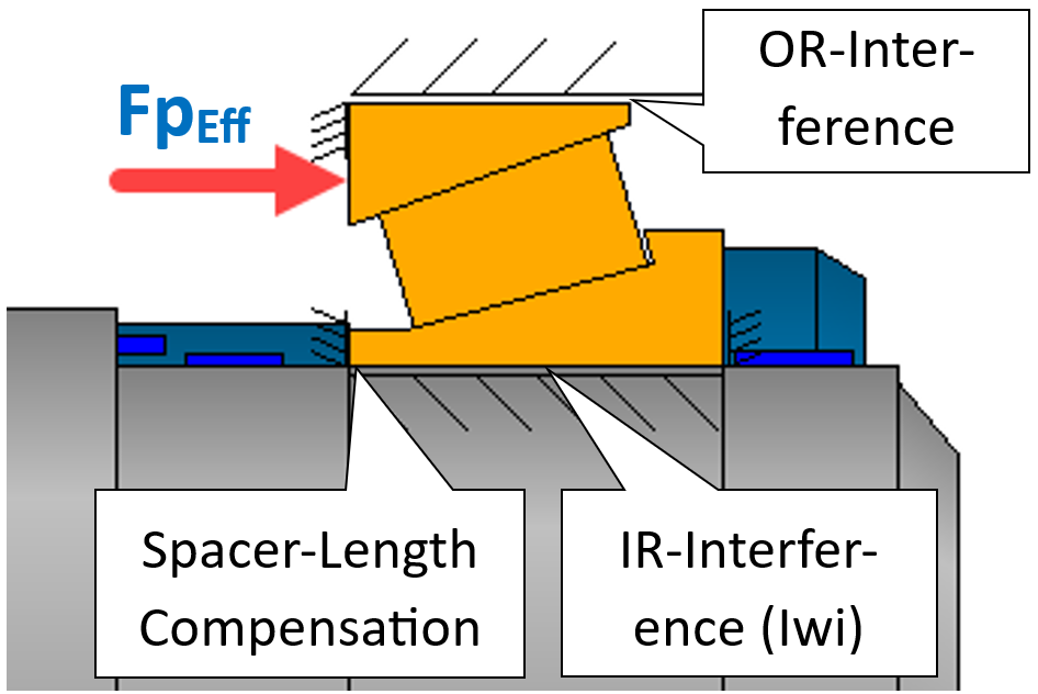
Figure 15
The bearing preload force (FpEff) is the dominant component of the total clamping force to be applied to the bearing pair. If an appropriate, compensating spacer length can be determined for each combination of the fit tolerance zones of both bearings, the effective bearing preload force FpEff may be assumed to remain constant. Such a solution approach can be obtained using the optimization function within the parameter variation and thus represents a useful aid for series production.
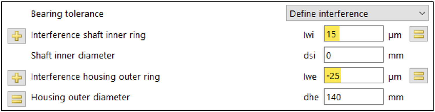
Figure 16
Reference case:
A reference case (Figure 16) with the spacer length set to the midpoint of the tolerance zones at both bearings is to serve as a guide for determining the required spacer-length adjustment in each situation.
List generation:
A practical discretization of the start and end values of the fit interferences is intended to enhance the clarity of the results (Figure 17).
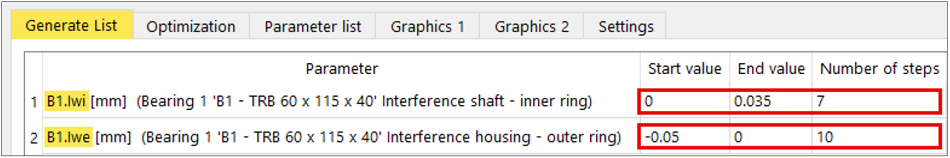
Figure 17
Optimization:
Within Parameter variation, MESYS provides the optimization option ‘Minimize input based on conditions’. This allows a selected input variable to be minimized under additional rules and constraints. The function is suitable for minimizing the delta spacer lengths PaLi and PaRi (Figure 18).
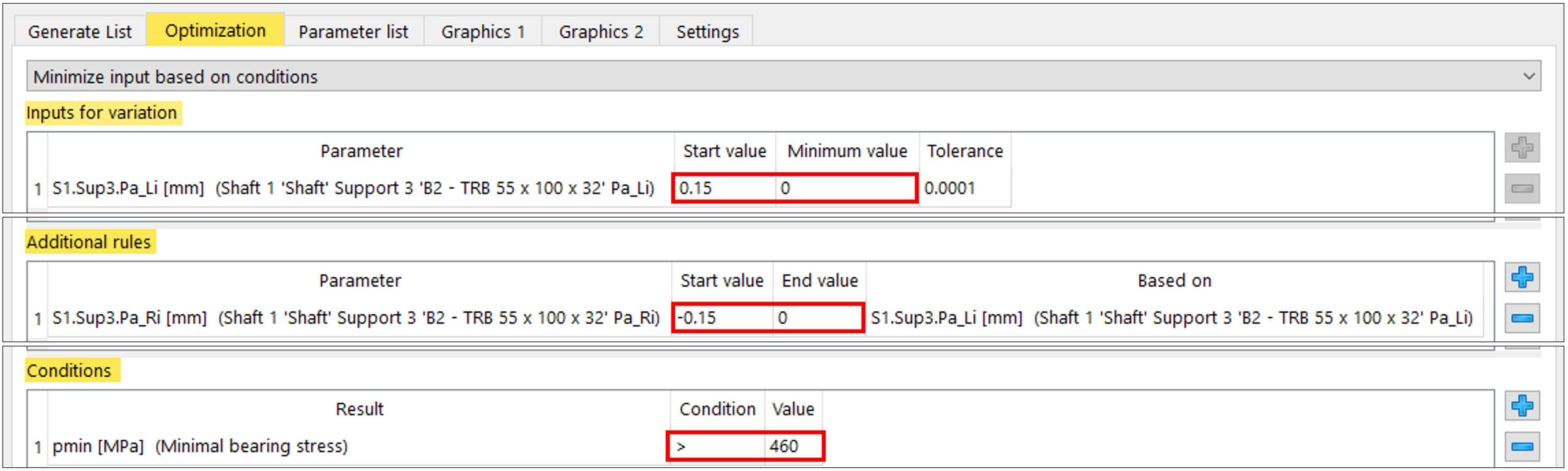
Figure 18
The parameterization is to be performed separately for bearings B1 and B2, taking the load spectrum into account.
Export:
Using the Export command (Figure 19), the B1 and B2 parameter lists can now be exported and further processed in Excel (Figure 20).
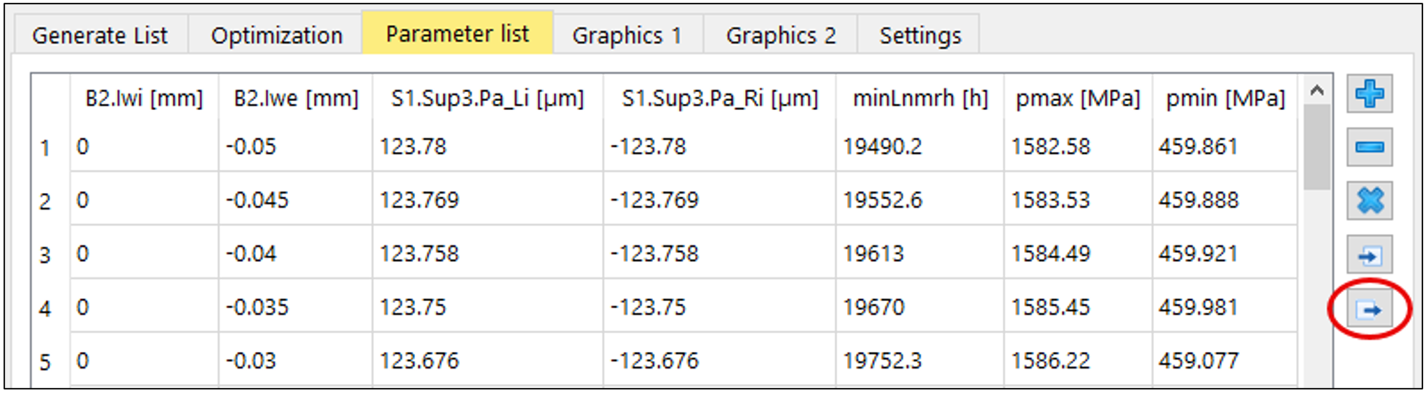
Figure 19
The incremental representation can be transposed into a matrix (Figure 20) and, in a subsequent step, converted into rounded approximate values for practical use:
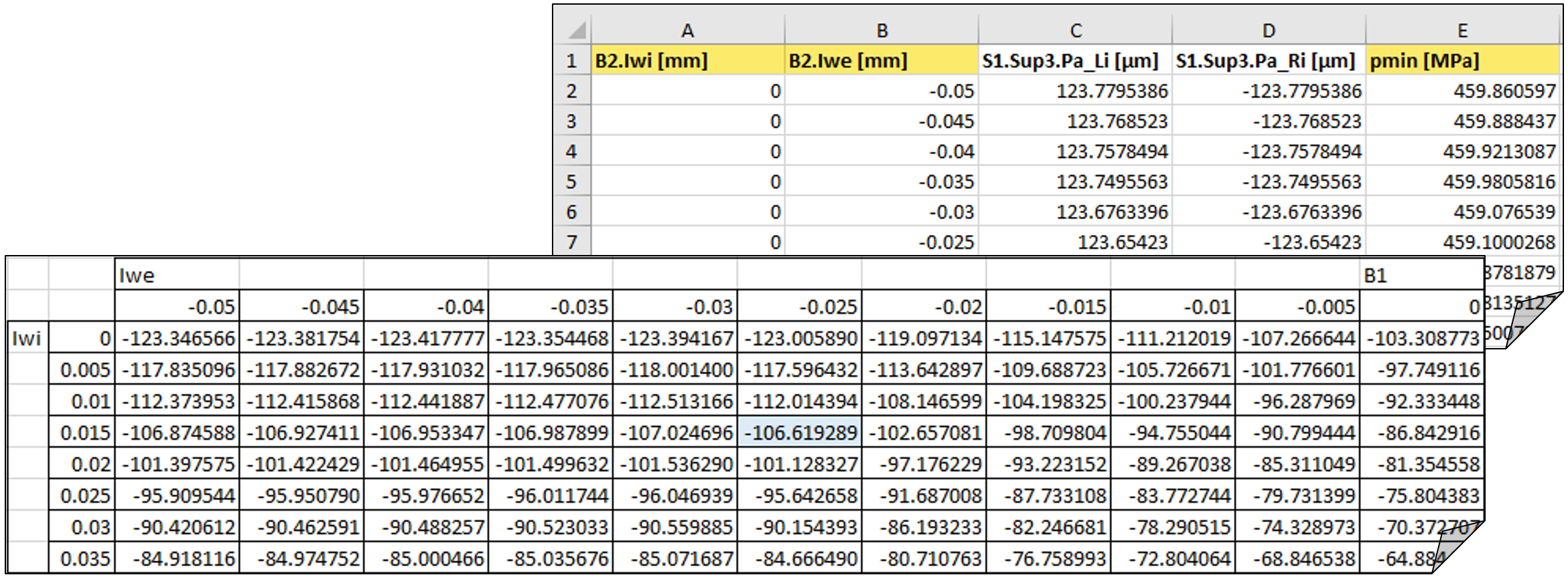
Figure 20
This allows a practical matrix to be created for both tapered roller bearings, which outputs the deviations from the nominal dimension of the spacer as a function of the actual dimensions of the shaft segment and bearing (Table 3):
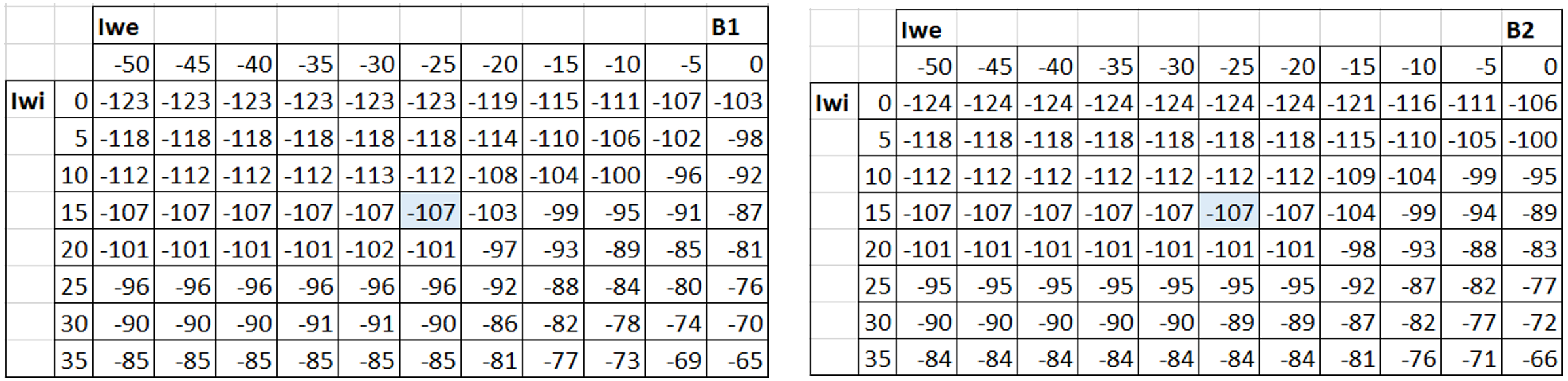
Table 3
4.5.4 Spacer calculation
The spacer length can now be determined approximately from the respective deviations relative to the reference case, as shown below.
Spacer length by iteration in the reference case
Under the reference fit interferences (Figure 16) and with the load spectrum activated, the deviation of the spacer length from the nominal value can be obtained by a pointwise manual iteration to reach pmin = 460 MPa (Figure 21).
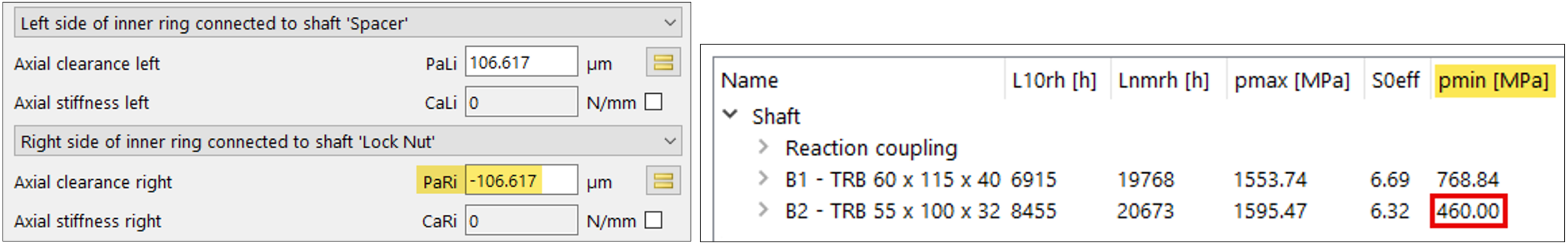
Figure 21
Hereafter, this quantity is referred to as the ‘deviation of the spacer length from the nominal value in the reference case’, abbreviated PaRiRef.
Spacer length via mean value in the reference case
PaRiRef can also be approximated by the mean of the two computed PaRi values for B1 and B2 (Table 3), which, when rounded under this approach, likewise yields -107 µm.
Spacer length for deviation from the reference case
Starting from Table 3, a more manufacturing-oriented matrix can be created that shows only the ‘deviation relative to PaRiRef‘. If the latter is designated delta_PaRiRef and PaRi is the tolerance position with PaRiTol, the placeholder of the matrix for PaRiRef is compensated by -107 (Table 4). If PaRiTol is ≙ PaRiRef in the specific tolerance field case, delta_PaRiRef = 0:
ΔPaRiRef = PaRiTol – PaRiRef
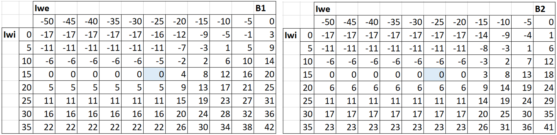
Table 4
Determination of the target spacer length
If the reference spacer length is designated RSL, the target spacer length TSL, and the nominal spacer length NSL, the following relationships apply:
RSL = NSL + PaRiRef = 20 + (-0.107) = 19.893 mm
TSL = RSL + B1.ΔPaRiRef + B2.ΔPaRiRef
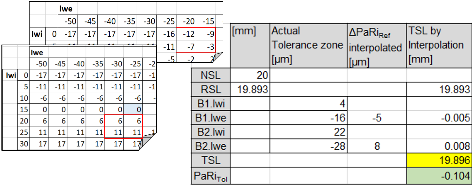
Table 5
The example on the right shows the practical determination of the spacer shortening using the simplified matrix from Table 4 and bilinear interpolation (Table 5):
Performing the calculation using the tolerance zones and spacer reduction from the above example shows that the minimum load requirement of 460 MPa is met (Figure 22).
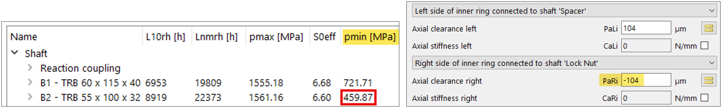
Figure 22
4.6 Locknut clamping force
4.6.1 General
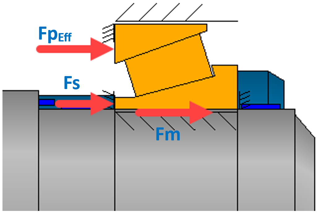
Figure 23
The required locknut clamping force should, as a matter of good practice, be determined in the assembly condition, i.e. load-spectrum element 1. It is usually obtained in the course of calculating the tightening torque for the locknut. The approximation pursued here combines the assembly force (cold), the bearing-pair preload force, and an additional retaining force to form the required total clamping force (Figure 23).
- Mounting (assembly) Force Fm
- Bearing-pair Preload Force FpEff
- Supplementary retaining Force Fs
4.6.2. Mounting Force
The mounting force (Fm) is to be quantified only at the inner fit (Ffit_i; Table 6). If the bearings are assembled without a temperature differential, the assembly force can be omitted.
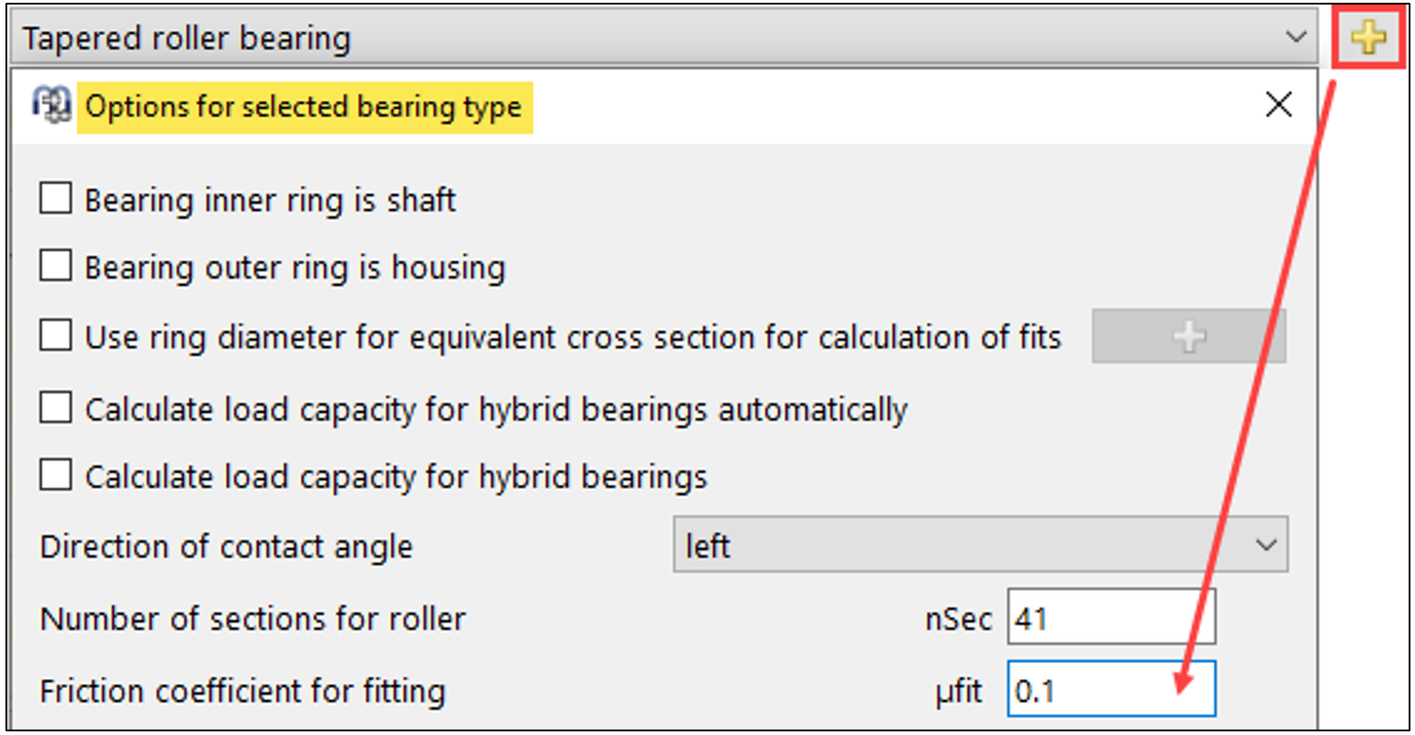
Figure 24
Friction coefficient
If an assembly friction coefficient is defined in the bearing options (Figure 24), the tolerance report also displays an axial assembly force.
Specific mounting force
The tolerance report for bearing B2 can be used to display the mounting force directly (Table 6).
The assembly force (Fm) can be read here as minimum-to-maximum values and reflects the selected fit tolerances, with elastic ring expansion taken into account. The values in Table 6 refer to B2 in load-spectrum element 1 under the iterated reference case (Figure 21).

Table 6
Assembly force as a function of tolerance zones
The assembly-force information provided by the tolerance report is not sufficient as a basis for industrial production. MESYS offers the option of determining assembly forces by combining tolerance zones using parameter variation.
The exported parameter list from the spacer-shortening calculation for bearing B2 (Figure 19) enables the determination of the mounting force across all feasible combinations of fit-tolerance zones within the range. The associated effect of the axial force of the preloaded bearing pair can be treated as an adjusted value attributable to the spacer correction.
Parameters such as the mounting-force term B2.Ffit or the locknut axial load S2.Sup1.Fx can additionally be included in the list at this step (Figure 25).
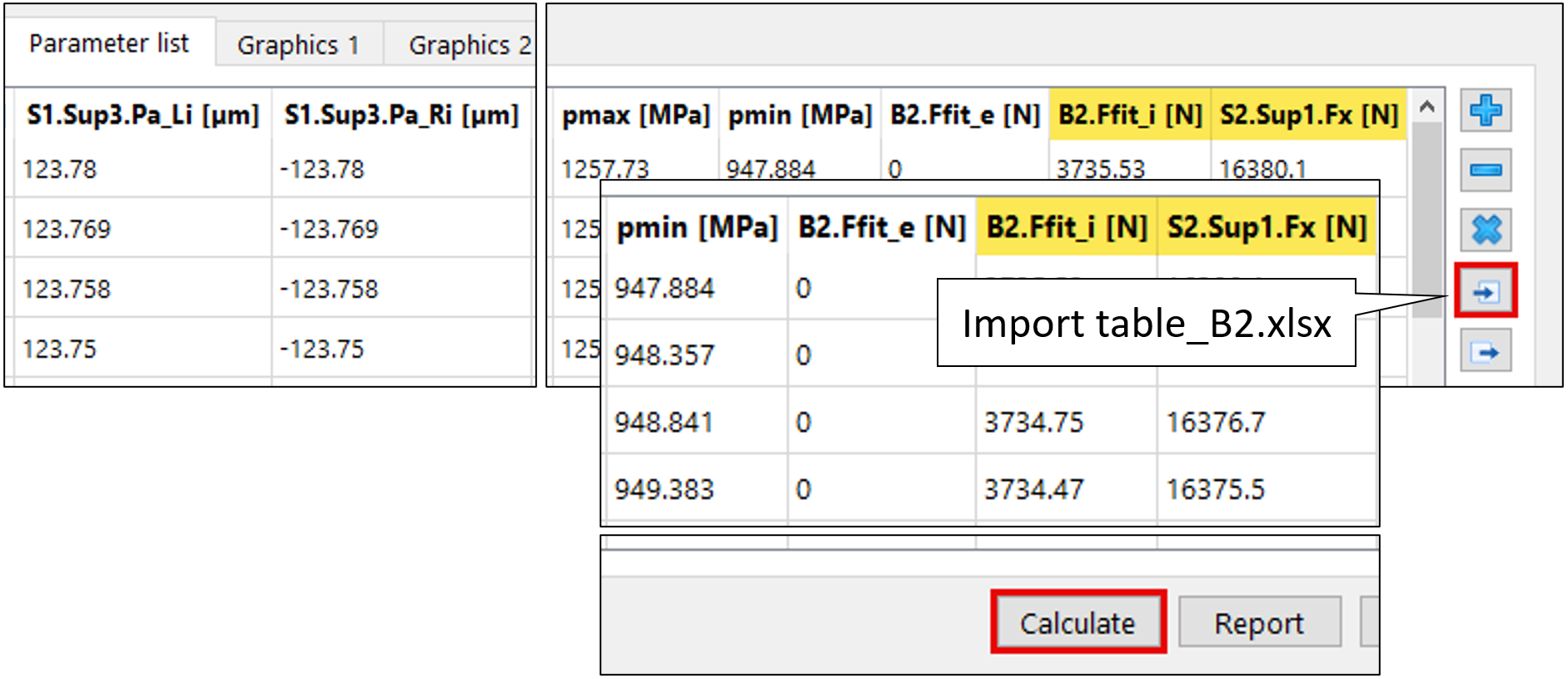
Figure 25
With load-spectrum element 1 (mounting) preselected, the imported file, once the calculation step is executed, yields the inner and outer assembly forces for B2 (Ffit) as well as the bearing-set clamping force at the locknut, S2.Sup1.Fx (Figure 25).
This adequately approximates the dependence of the assembly force at bearing B2 on the fit interferences and the effects of the elastic ring expansion.
4.6.3 Supplementary retaining Force
In practice, a supplementary retaining force (Fs) is applied to the clamped block as a preventive measure to provide additional rigidity to compensate for dynamic force introduction. Here, a value for the contact stress (N/mm2) at the interference with the spacer can be selected based on bearing manufacturer specifications or an empirical approach.
For the present case Fs, as a summand to the locknut clamping force, is set to 8’000 N.
4.6.4 Total clamping force
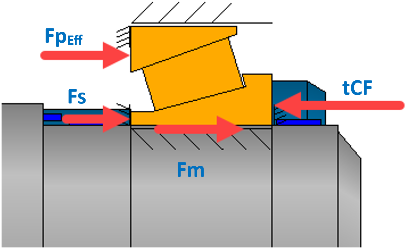
Figure 26
The sum of the targeted locknut clamping force (tCF) (Figure 26) from the effective preload force of the bearing pair + assembly force + additional holding force is now as follows according to the afore-mentioned definition:
tCF = Fm+ FpEff + Fs
By adding a fixed value for Fsin accordance with 4.6.3 to an export file (Figure 27), a practical tool is now obtained for quick determination of the locknut clamping force corresponding to the specific spacer length.
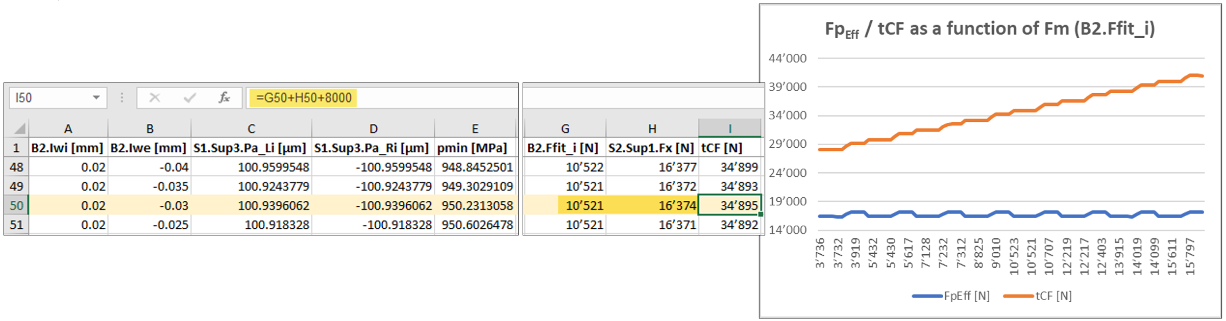
Figure 27
The graph in Figure 27 shows that, with the spacer adjustment applied, the effective bearing preload FpEff (S2.Sup.Fx) remains essentially constant with respect to the inner assembly force (B2.Ffit_i). This behaviour does not change when deviating from the reference tolerance condition at bearing B1. The approach described in 4.5.4 takes into account a corresponding spacer adjustment under the effect of both bearing seats. Accordingly, as a qualitative approximation, deriving the required lock-nut clamping force as a function of the tolerance-zone variation of the preloaded bearing B2, together with rounding or interpolating the parameter list imported in 4.6.2, can be regarded as an appropriate approach.
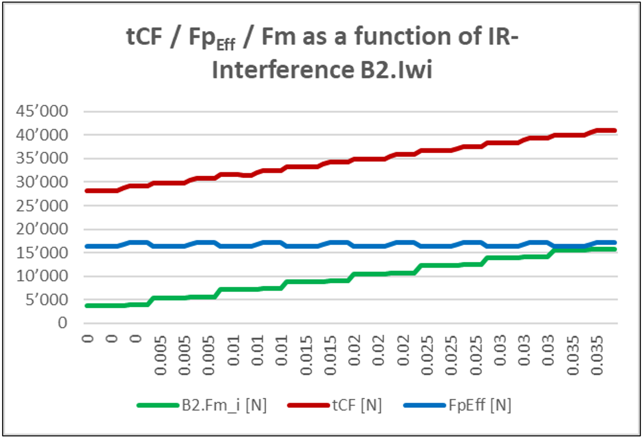
Figure 28
The summands of the lock nut clamping force Fm + FpEff + Fs can be rounded or interpolated individually. Due to the spacer adjustment across all tolerance zones – including at the outer interference – the bearing preload force FpEff remains virtually constant (Figure 28). The function of the variation in the necessary total locknut clamping force tCF can therefore be found in the mounting force on the inner ring. It follows that the outer tolerance position and its interference (Iwe) are not relevant here and that a one-dimensional consideration is entirely appropriate in practice.
For the specific tolerance condition, the assembly force Fm is 10’521 N and the effective bearing preload FpEff is 16’374 N. This yields a locknut total clamping force tCF of 34’895 N (Figure 27).
5. Effect & verification
5.1 Example
Based on the example calculation of the spacer length in 4.5.4, a locknut clamping force is to be determined. The spacer reduction (‘withdrawal’, Table 4) was determined to be -104 µm for a target spacer length SSL of 19.896 mm.
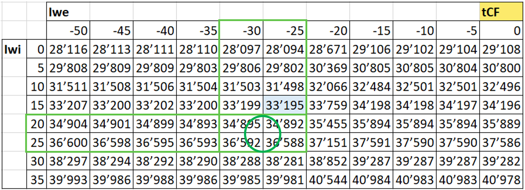
Table 7
Bilinear interpolation of tCF
The table converted to a matrix representation and generated in 4.6.4 serves as the basis for determining the locknut total clamping force tCF (Table 7).
The resulting clamping force tCF, obtained by the corresponding interpolation, is 35’572 N.
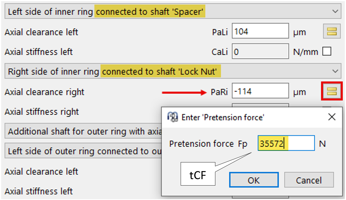
Figure 29
Since the lock nut clamping force is now known, it can be entered in MESYS via the PaRi ‘=’ – icon button to compute the required spacer-length adjustment (Figure 29).
Note: The locknut clamping force can also be prescribed as a boundary condition at the locknut itself.
5.2 Results
After entering the values corresponding to the example above, the lower pane of the user interface (Figure 30) displays the expected axial forces, contact pressure, and service life.
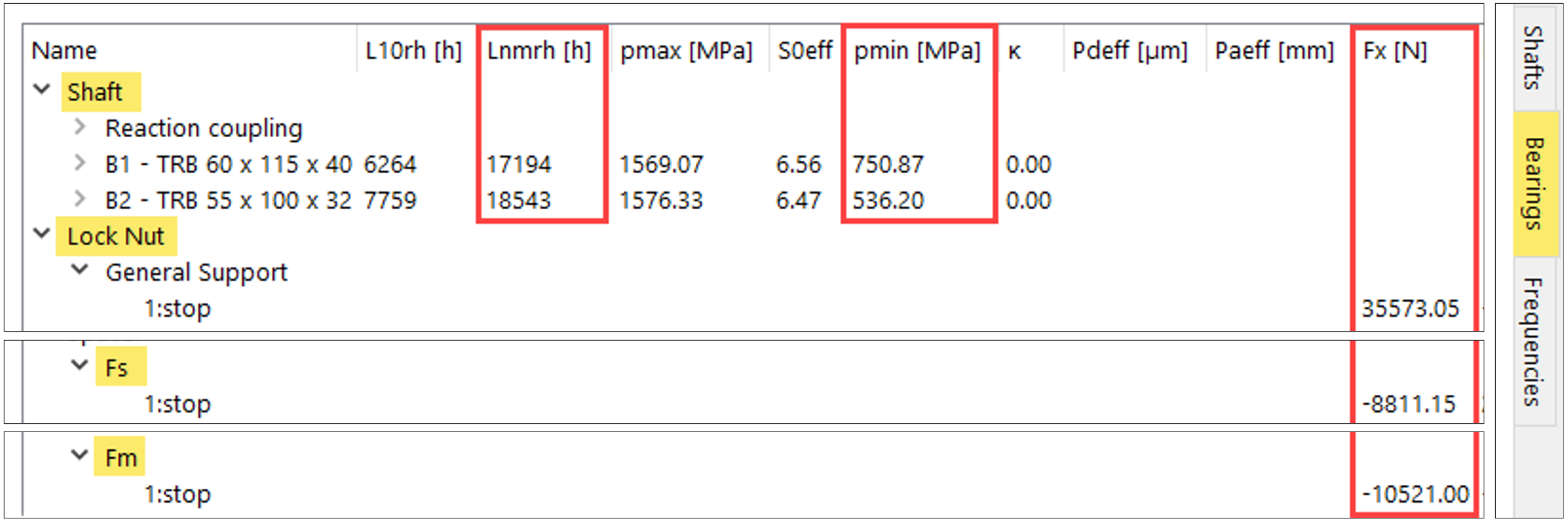
Figure 30
5.3 Verification
The following can be mentioned with regard to the arguments for design objectives across the entire load collective:
- The minimum load is maintained
- The minimum service life is maintained
- The contact force of the shaft nut is specifically designed
- The approximation methods described above are robust across fit tolerance zones
5.4 Further remarks
The design of a preload and adjustment of a tapered roller bearing pair described here does not claim to be exhaustive. The derivation of the preload depends on assumptions which have to be adjusted to the respective application. The bearing stiffness depends on their internal geometry, which is often unknown to the end users.