The calculation for cylindrical gear pairs can be used as standalone program or integrated into the shaft system calculation. Following features are included:
- Gear geometry calculation according to ISO 21771-1. For internal gears all input and output diameters are used as positive values in the software as they are used for manufacturing and documentation. Only the number of teeth for internal gears is set to a negative value.
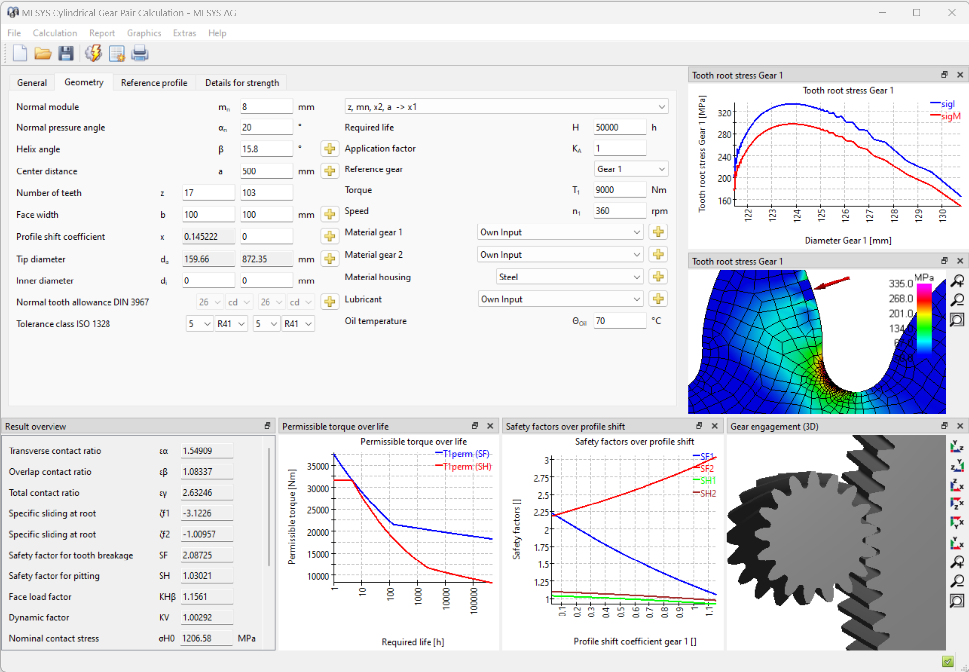
- Gear strength calculation according to ISO 6336 parts 1, 2, 3, 5, 6, 20, 21. Different options are available for the tooth thickness and contact ratio to be used.
- Support for load spectra. In addition to speed and torque also mesh deviations, face load coefficients or mean stress influence factors can be defined in the load spectrum.
- Parameter variation to vary geometry or loading with output in tables and diagrams
- Tooth form graphics for single teeth, full gear, manufacturing or engagement
- Graphics for specific sliding, safeties over life, permissible torque over life
- FEA based tooth form stress using 2D-FEA. For helical gears either the virtual spur gear can be used or the normal section.
- 3D-Gear geometry available as STEP export. The transverse section is generated with a accuracy better than 10-4*mn*cos(β) and then extruded along a helix. Accuracy along the helix depends on the CAD system. Currently no profile or flank modifications are included.
The eight calculation examples from ISO/TR 6336-30 are included in the installation.