


Purpose and Objectives
The load limit diagram of a motor spindle serves to graphically represent the permissible operating range as a function of parameters such as rotational speed. It enables a quick assessment of the conditions under which the spindle can be operated safely and reliably without exceeding mechanical, thermal, or dynamic limits. Such a diagram is a key tool for the design, selection, and evaluation of spindle systems in mechanical engineering – particularly in the field of machining, where high demands are placed on precision, performance, and service life.
The same methodology can also be applied to electric motors in general, where torque, speed, thermal, and structural limits likewise play a central role in design and application. Whether in machine tools, robotics, automotive engineering, or industrial drives – a systematically developed load limit diagram provides a solid foundation for the safe and efficient use of the motor at its intended operating point.
To better understand these interrelationships, this technical essay aims to explain the systematic derivation of a load limit diagram. It addresses both the physical fundamentals and the practical limitations arising from bearing arrangement, drive system, cooling, and structural design. The objective is to identify the key influencing factors that determine the spindle’s limit behavior and to present them in a transparent, simulation-based format using MESYS.
Initial Situation
Specification:
The investigated hypothetical application is a high-speed motor spindle for aluminum machining, with a maximum torque of 10.75 Nm and a maximum rotational speed of 36,000 rpm. An HSK-F63 interface is used as the tool holder. The applied tool radius is r = 12 mm, corresponding to an end mill with a diameter of 24 mm.
Bearing Concept:
The spindle is supported by two spring-preloaded O-arranged tandem bearing sets, each consisting of a front and a rear bearing pair. The following bearing configurations are used:
– Front bearing pair: 7010, contact angle = 18°
– Rear bearing pair: 7010, contact angle = 18°, spring-preloaded with 1300 N
This arrangement corresponds to a typical configuration for high-speed motor spindles. It allows for the accommodation of thermal expansion in the axial direction while maintaining high stiffness and performance capacity.
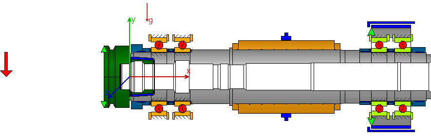
Mounting Orientation:
The spindle is horizontally mounted, which prevents the front bearing set from being unloaded by gravity. This positional effect is considered in the calculation.
Influencing Factors Requiring Limitation
Mechanical Limits
• Maximum speed: Limited by bearing capability, rotating parts, centrifugal forces, or balancing quality
• Maximum torque: Limited by motor, windings, rotor structure, or inverter performance
• Tangential tool force: Induces bending moment in the spindle
• Radial force: Degrades spindle kinematics
• Axial force: Especially critical when negative
• Combined radial/axial load: Leads to asymmetric bearing loading
• Spindle orientation: In vertical position, gravity may unload front bearing set
Bearing-Related Limits
• Bearing misalignment: Affects kinematics and contact pressure
• Hertzian contact pressure: Influences fatigue life
• Spin-to-roll ratio: Affects kinematics
• Ball lead/lag: Affects kinematics
Thermal Limits
• Rotor power loss: Temperature gradient across shaft segments
• Bearing seat heating: Temperature gradient alters preload, kinematics, and bearing life
• Thermal expansion: Affects the compensation or behavior of the bearing pair
Methodology for Limit Curve Determination
For the present study, a set of exemplary limiting conditions is defined in order to generate a technically consistent load limit curve for the motor spindle. These conditions serve illustrative purposes and enable a transparent delimitation of the permissible load range as a function of rotational speed. Naturally, more complex and realistic criteria may be considered in subsequent studies for the generation of, for example, a full load limit map.
For the simulation described, a worst-case load scenario was defined at three working positions with axial distances from the spindle nose of x = –80 / –100 / –120 mm:
• Tangential force: 100%
• Axial force: –33%
The following limit states are considered in the simulation:
• Minimum Hertzian pressure: pmin > 500 MPa
• Maximum Hertzian pressure: pmax < 2000 MPa
• Spin-to-roll ratio: < 0.3
• Maximum transferable torque: Mx < 10.75 Nm
MESYS Parameterization and Evaluation
The MESYS Shaft Calculation module is used to determine the load limit curve. The optimization function for parameter variation “maximize input based on conditions” is applied to determine the maximum permissible loads while complying with defined limit values.
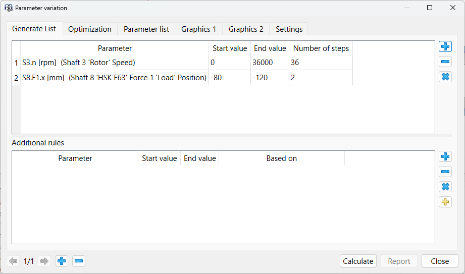
Parameter list
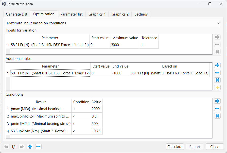
Optimization criteria
The software iteratively increases the load as long as all limit conditions can still be met simultaneously. In this way, a maximum permissible force combination is determined for each speed level.
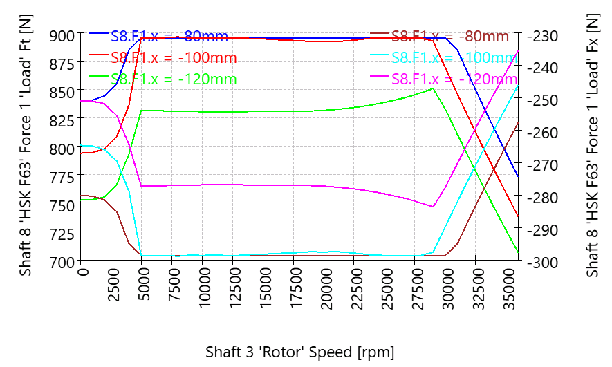
Contact pressures min. / max.
=> pmin limits x = –100 mm up to 4000 rpm
=> pmax limits x = –100 mm between 13000 and 24000 rpm
=> pmax does not limit x = -80 mm
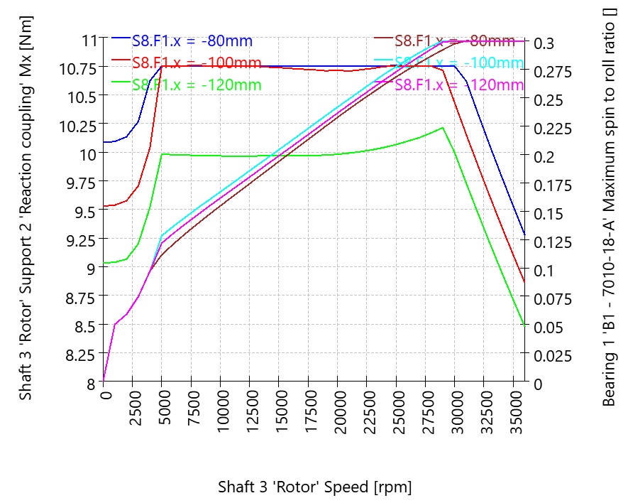
Output Torque and Kinematics at Rolling Bearing 1
=> Mx limits x = –100 mm from 5000 to 12000 rpm and from 25000 to 28000 rpm
=> Spin-to-roll ratio limits x = –100 mm at B1 from 29000 to 36000 rpm
=> The motor power cannot be fully exploited at x = –120 mm, as pmax is the limiting factor
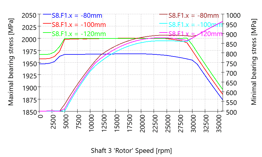
Results and Interpretation of the Load Limit Curve
The resulting load limit diagram shows the maximum permissible load on the motor spindle as a function of rotational speed, while complying with all previously defined limit conditions.
Key findings from the curve envelopes:
At low rotational speeds (< 5000 rpm), the load is limited by falling below the minimum bearing pressure. This is intended to prevent bearing tilting and potential loss of contact.
In the range between approximately 5,000 and 30000 rpm, a wide usable band emerges in which the spindle’s load capacity can be largely exploited without reaching critical bearing conditions. This range is therefore considered an economically efficient operating window.
From around 30,000 rpm onward, the spin-to-roll criterion at rolling bearing 1 becomes the limiting factor, as radial loads at very high speeds can disturb the bearing kinematics and lead to associated issues.
Load Limit Diagram
Overall, the generated load limit curves clearly illustrate both the design reserves and the physical limitations of the spindle. They provide a basis for defining suitable application ranges, planning machining strategies, and avoiding critical overloads.