


Often single values are used for radial or axial stiffness of a rolling element bearing. For some bearing types and load conditions this might be sufficient, for others it is not.
What is a stiffness? Generally, a stiffness describes the change of a force for a change of displacement. Dividing a force with the displacement c=F/u is only valid for linear systems, instead a gradient or differences should be used, like c=ΔF/Δu for a given operating point. The stiffness of rolling element bearing gets nonlinear because of clearance and because of the nonlinear Hertzian contacts between rolling elements and races.
Is this a sufficient definition for a bearing stiffness? Unfortunately, not. Assuming rigid bearing rings there are displacements in 3 directions and rotations around two axes which leads for forces or moments. So a 5*5 stiffness matrix can be defined containing 25 numbers. The best would be to use this full stiffness matrix for FEA or rotor dynamic calculations.
If a single number for a radial stiffness should be defined, the main diagonal at the y-position of the stiffness matrix seems to be a reasonable choice, but there are other possibilities. The main diagonal of the stiffness matrix is the stiffness you get when calculating cyy=ΔFy/ Δuy for fixed displacements and rotations ux, uz, ry, rz.
Another possibility to derive cyy=ΔFy/Δuy would be to change Fy and measure Δuy for fixed forces Fx, Fz and fixed moments My, Mz. Or you derive cyy=ΔFy/Δuy using fixed forces Fx, Fz and fixed tilting angle ry, rz.
Each of these methods leads to a different radial stiffness. For an angular contact bearing with contact angle 15° and axial force Fx=500N and varying radial force Fy the following three values for radial stiffness cyy=ΔFy/Δuy are derived:
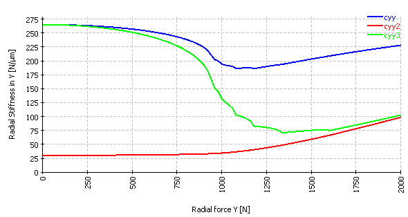
The radial stiffness is initially decreasing for the upper two curves, because some rolling element have reduced load or loose contact on increased radial load.
For axial stiffness the same can be calculated:
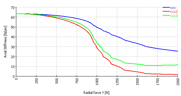
The blue curves are the main diagonal of the 5*5 stiffness matrix. The red curve is the reciprocal of the main diagonal of the 5*5 compliance matrix. The green curve is the reciprocal of the main diagonal of the 3*3 compliance matrix which is only considering translation degrees of freedom and no rotations.
For the radial stiffness a factor of 10 can be seen between the different stiffness values. Mostly the red curve wouldn’t be a relevant case, but the differences between the blue and green curve can get quite large too. As example for the tree cases of radial stiffness, the blue curve would fit to angular contact bearings under rigid pretension, the green line would fit to angular contact bearings with spring pretension and the definition of the red curve without axial pretension could fit to track rollers.
So generally, the full stiffness matrix of a bearing should be considered, which is dependent on the load and for high speed also speed dependent.