Elastic housing deformation can have an impact on the load distribution within rolling element bearings. For many applications this is neglectable, but for large bearings or soft housings, it can be of interest to consider this effect.
The MESYS shaft system calculation could take into account housing stiffness based on a global matrix or an import of a STEP-file or a FEA-mesh for several versions. The housing stiffness was considered as one node at the center of each bearing ring. The ring itself was still cylindrical or has user defined deformations.
At the Hannover fair 2018 at booth G22 in hall 6, MESYS AG presents a preview of the MESYS shaft system calculation, which considers a coupling between housing deformations and deformations of bearing rings. The housings can be imported as STEP-model or they can be defined parametrically for simple rotation symmetric cases. The STEP-model is then meshed and statically reduced. Optionally a modal reduction is possible too.
As simple example first a deep groove ball bearing in a rectangular block, which is fixed at the bottom side. The bearing is loaded horizontally.
On the left the deformations and the load distribution with consideration of elastic deformations of the bearing ring, on the right one the averaged deformation of the housing is considered with a circular bearing ring:


The maximum contact stress is 3285MPa with elastic ring and 3175MPa with rigid ring. The horizontal displacement is 0.052mm with elastic ring and 0.051mm with rigid ring. The vertical displacement is 0.01mm with elastic ring and zero with rigid ring. The vertical uplift is only visible using the elastic model. As comparison the horizontal displacement without housing stiffness, which would be 0.032mm.
While the contact stress is independent on the load direction using the rigid ring, there is a dependency of contact stress from load direction using the elastic ring:

With a force angle of 0° (force to the top) the lowest contact stress results, while the maximum stress results at about 110° load direction. The overlaid variations in the curve have their reason the fixed positions of the rolling elements in the calculation.
For this example, a bearing clearance of zero was considered. Using a larger clearance would lead to higher contact stress for the cylindrical ring.
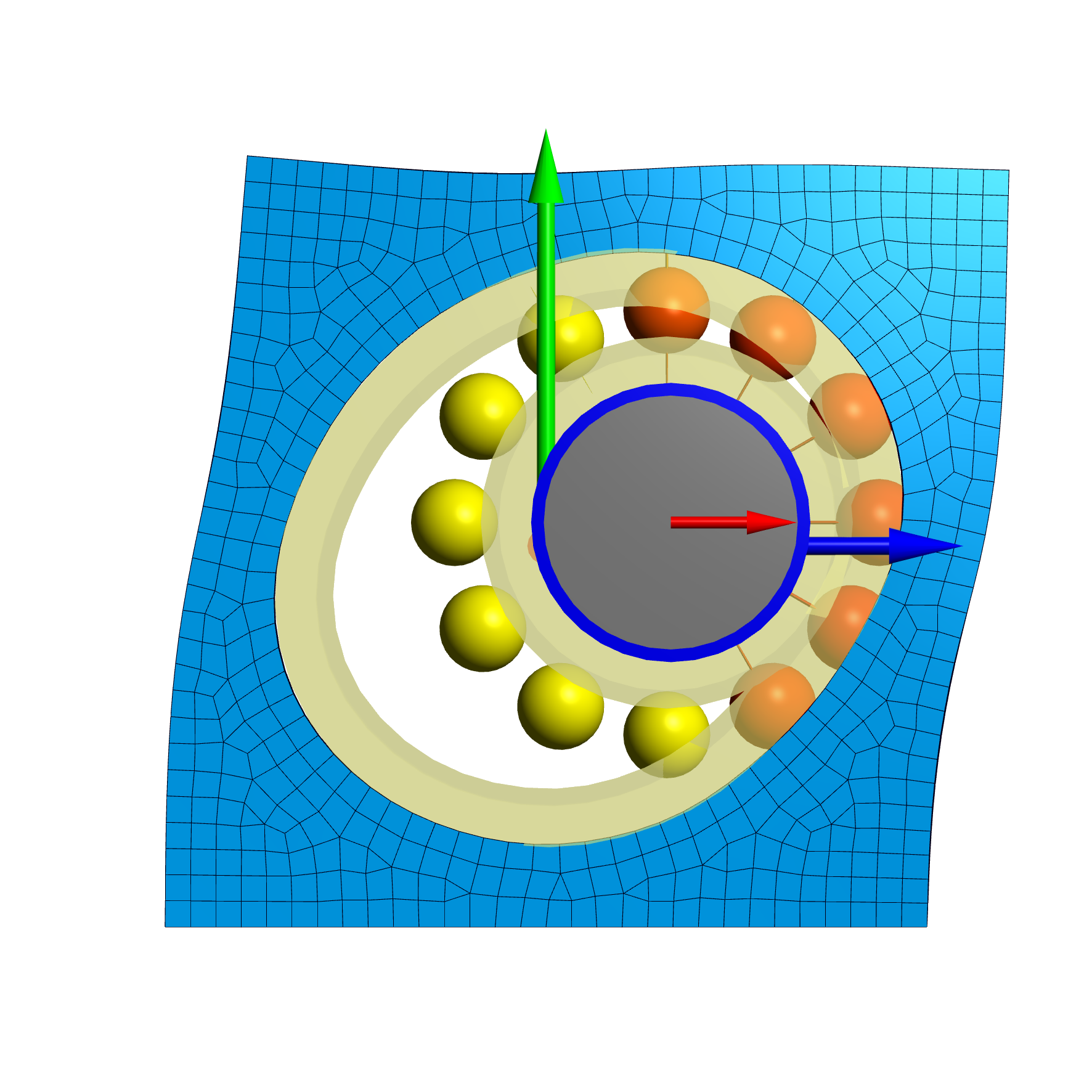
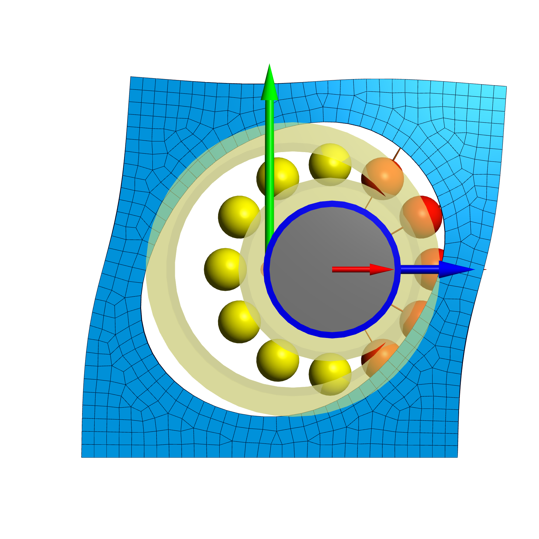
Cross roller bearing example
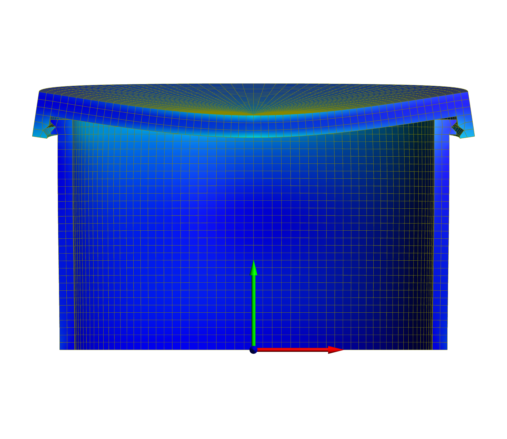
As second example a cross roller bearing under axial, radial and moment load is considered. The loading acts on the upper surface and the lower cylinder is fixed at the bottom face.
The contact stress is shown for three cases. First a full calculation with 3D solid elements without reduction, then for a bearing with rigid rings and a calculation with reduced FEA-model in the shaft system calculation.
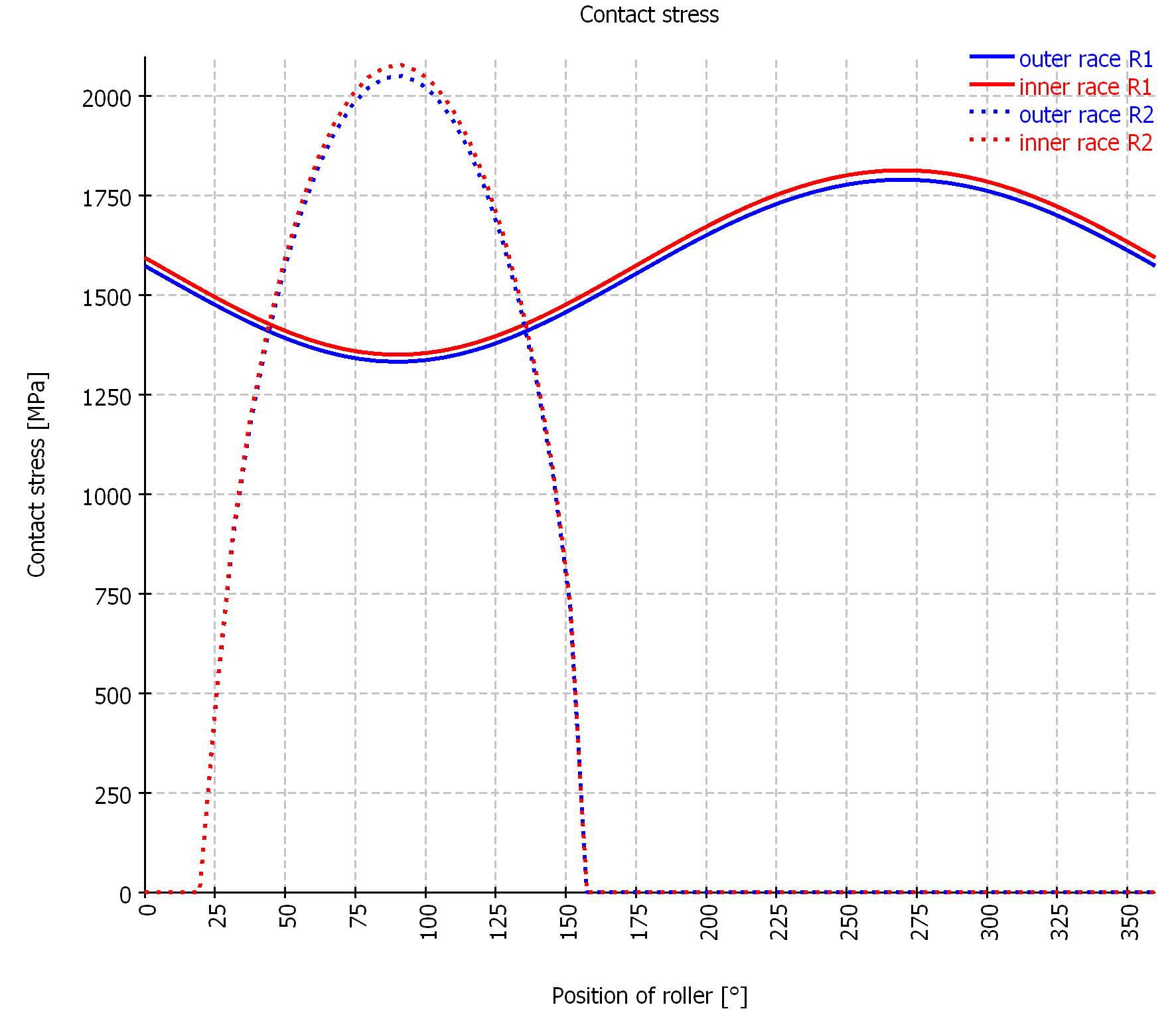
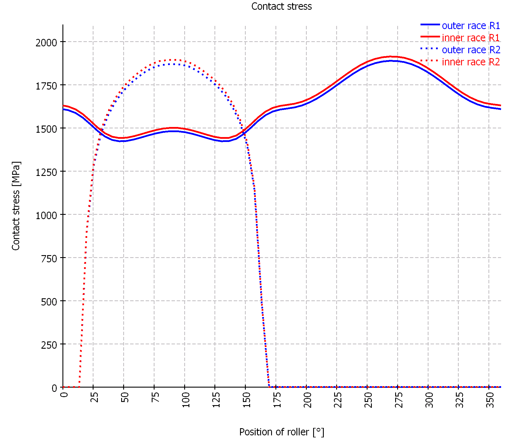
The maximum contact stress is 1941MPa for the full 3D-model, 2078MPa for the bearing with rigid rings and 1917MPa for the reduced model. A larger difference is seen at the rolling element forces which are 3734N, 4540N and 3719N.
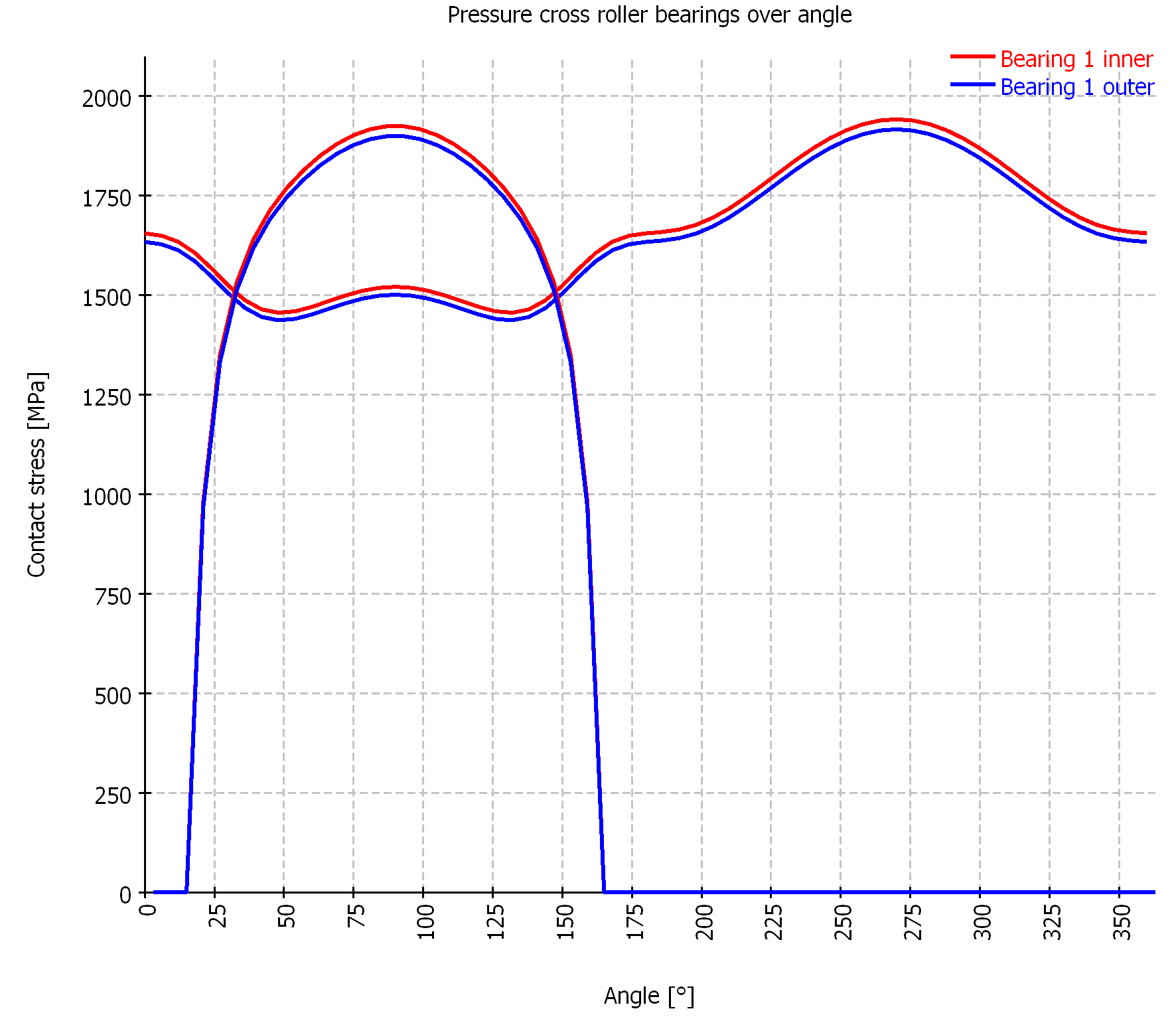
The curves for the contact stress for the two elastic cases in above diagrams show the same shape with maxima of both races at the same level. In case of the rigid rings one race sees a higher contact stress. A comparison of the axial deformation is difficult because of the large deformation of the top. For the radial displacements there is a result of 0.03mm for the rigid case and an average radial displacement of 0.2mm (0.19mm) in the elastic cases (the average value is determined differently in both cases).
In many cases the deformations of the bearing rings lead to a larger load zone and therefore to a smaller contact stress.
The full 3D-model is a little software than the reduced model as the reduced model uses the same tilting angle for both races in a ring. The reduced model does currently only consider global ring deformations, but no deformation within the ring. This is a special case for a cross roller bearings as it contains two rows.
A calculation using the full 3D model takes a little more than 3 minutes, while a calculation for one load case of the reduced model only takes less than a second. The full 3D-model would allow to consider nonlinearities like contact, while the reduced model is a linear stiffness matrix only.
A preview version is available at the Hannover fair, the final version with coupling of housing stiffness and elastic ring deformations will be available with version 08/2018 in autumn.