There are some settings available for the 3D-elastic parts.
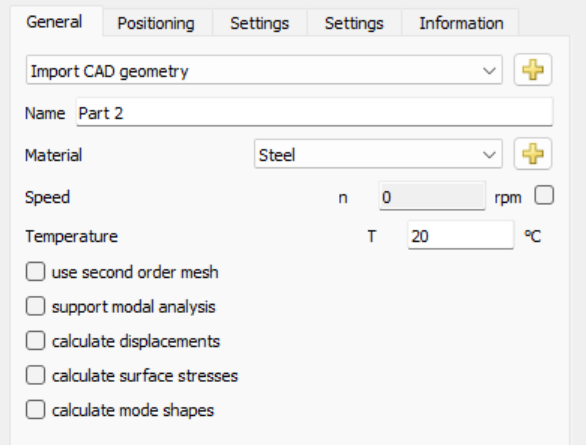
On page "General" the material, speed, temperature can be defined. A change of material requires a new reduction for the part.
There are two pages for settings. All settings on the first page do not require a new condensation and all settings on the second page require a new condensation.
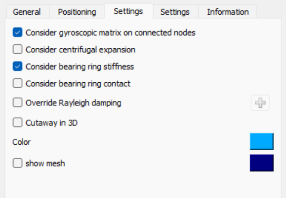
The color for the part and the mesh can defined which is used in the standard 3D-geometry views.
The reduction of the 3D-elastic parts lead only to mass and stiffness matrices. No gyroscopic matrix is considered. As approximation the polar inertia can be considered a gyroscopic matrix on the connected reduced nodes on the x-axis. The polar inertia will be distributed equally on all available nodes if the option"Consider gyroscopic matrix on connected nodes" is set.
The option "Consider centrifugal expansion" will add the effect of centrifugal expansion to the part. This is only active for 3D-elastic shafts.
The option "Consider bearing ring stiffness" will add the stiffness of the bearing rings to elastic bearings. If the ring is already included in the 3D-elastic part, this option should be disabled. Using "Consider bearing ring contact" will add a contact model between bearing ring and part. Then the fitting calculation will not directly set an operating clearance of the bearing, but the fitting will be influenced by expansion or compression of the elastic parts. If the stiffness of the part is not uniform, there will be already a deformation of the bearing ring after mounting.
The option "Override Rayleigh damping" allows to define a different Rayleigh damping for the 3D-elastic part than for the global system.
Activating the option "Cutaway in 3D" will lead to a cut view in the 3D-view for the system like the same setting available for shafts.
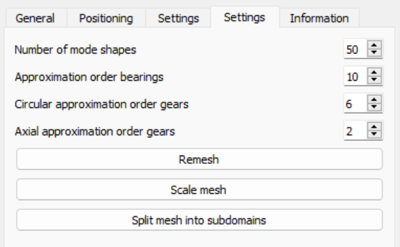
On the second page "Settings" the number of mode shapes used for modal reduction can be defined. A larger number increases accuracy but required more memory and reduction time. Usually a value larger 20 should be used. The maximum frequency is shown on page "Information". This frequency should be larger than the maximum frequency that is of interest for the system.
An approximation order for elastic bearing rings and elastic gears can be defined here. The transverse approximation order for gears of 2 means a parabola is used for transverse deformations. A factor of 1 would only use a straight line. For gears with a large face width larger orders than 2 might be appropriate. The approximation order can be overridden using the contact menu in the table for faces.
The button "Remesh" allows to remesh the part. Either to change the mesh size or the type hexahedral/tetrahedral. Note that this is a remesh of the previous mesh, generally it would be better to do a new import of the CAD file in case the mesh size is changed. "Scale mesh" allows to apply a scale factor on the mesh. This could help, in case the unit system of the import was not correct. "Split mesh into subdomains" allows to split the mesh into subdomains based on selection of a cylinder or a box, for each subdomain then different material properties can be selected.The use of either button requires a new reduction of the part.