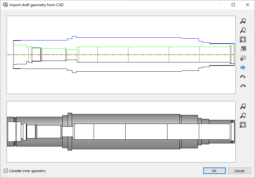
The shaft geometry can be imported from 2D DXF or 3D STEP files. In case of a 3D-STEP file an intersection of the part in the x/y-plane, the x/z-plane and the y/z-plane is done and the resulting edges are considered as in the DXF input. Relief grooves in the CAD model can lead to many imported elements.
For the DXF file a normal drawing can be selected. By using the left mouse button, some geometry can be selected. The selected geometry can either be deleted or it can be cut. This allows to select the correct geometry for the import. The  -button allows to switch through different layers within the DXF file or through different parts or sections in STEP import.
If an inner geometry should be imported too, the flag at the bottom of the window has to be activated.
The DXF file only contains lines. Sometimes the software cannot detect the correct connections between these lines. In this case the wrongly used lines can be selected and deleted. The lower part of the window shows the currently detected geometry input. Selecting some segments with undercut and pressing the key "c" allows to remove the undercut. Selecting two lines with a gap and pressing the key "c" allows to close the gap. Selecting two lines with the same axial start end end point and pressing the key "c" will add vertical lines which are used to define the position of the axis.