The geometry data of a shaft is defined on page “Geometry”. The geometry can be defined using cylindrical and conical elements for outer and inner geometry. The shaft geometry could also be imported from CAD files, see Import of shaft geometry from CAD files.
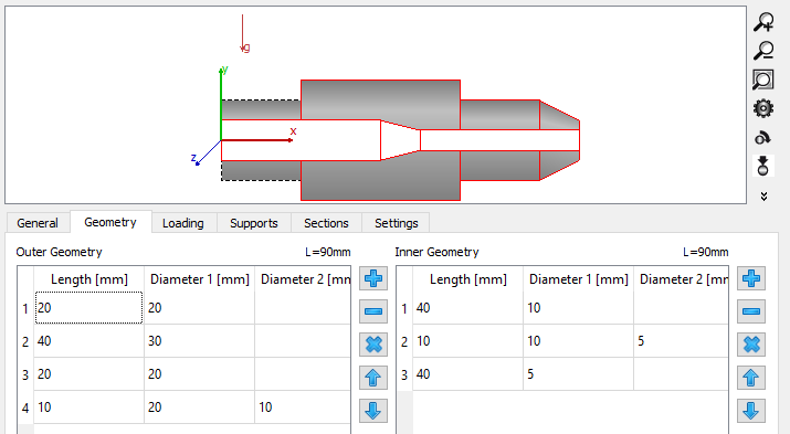
There is an input table for both inner and outer geometry. The plus and minus buttons allow adding and removing rows, the arrows can be used to move an element up or down in the table.
Length and diameter 1 have to be defined for each element. If diameter 2 is left empty, a cylinder is used else a cone. No negative values are permitted. The total length is shown above the table.
If a hole from the right shall be defined as inner geometry, enter a first element with diameter zero to get to the start position on the hole.
The dimensions of each element can also be changed in the view. Use Shift and left mouse button for it. For changing the length the click needs to be in the right third of an element. For changing the diameter it has to be in the upper third of an element. To change a cylinder into a cone element the mouse needs to be in the left third of an element. The interactive change is restricted to a 1mm grid. Using Shift and Control buttons will move the shaft instead of changing an element.
The table for outer geometry also allows an input for a temperature difference if the corresponding option under settings is activated.