The axial clearance Pa is shown for angular contact bearings, four-point bearings, cylindrical roller bearings and all axial bearings. The axial clearance is the difference between the possible axial displacement in positive and negative direction for-four point bearings and cylindrical roller bearings.
For single row angular contact bearings or tapered roller bearings, it is the axial distance between inner and outer ring when the bearing rings are moved together with a very small axial load. So in this case, the clearance is between center and one direction and for double row angular contact bearings, four-point bearings and cylindrical roller bearings, it is the maximum distance between left and right end positions.
For cylindrical roller bearings, a value larger than zero should be entered for the axial clearance, since the bearing usually has axial clearance. If the calculation is done with clearance zero, you will get some axial loads on the rollers if there is a tilting angle of the bearing. This should be the case for a locating cylindrical roller bearing, but not for a non-locating bearing. So the correct clearance should be entered in both cases.
A pretension can be entered by using a negative value for the axial clearance Pa. A  -button allows the input of diametral clearance instead of axial clearance for certain bearing types. For angular contact bearings or tapered roller bearings, the axial clearance can also be calculated for a given pretension force.
For roller bearings, the calculation of axial clearance from pretension force does not yet take into account the extended pressure calculation or changes of profiles.
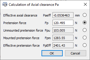
Dependent on the bearing type, several options for the pretension force are available. The calculation with “Fp” is using nominal dimensions for the bearings, the calculation using “Fpu” is using nominal dimensions together with a radial elastic expansion without limit; this option can be used for the case of loading an unmounted bearing axially during manufacturing. The mounted pretension force "Fpm" is calculated using the dimensions after fitting but no temperature or speed. The effective pretension force “FpEff” is calculated using the dimensions after fitting and considering temperature and speed.