The radial cylindrical roller bearing is a bearing providing a high load capacity for radial loads but it does not support high axial loads or misalignment of inner and outer ring.
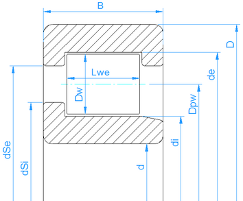
In addition to the parameters used for ball bearings, the effective length of the roller Lwe is a required input parameter. The effective length is a little smaller than the length of the roller because of radii at the end of the roller. The contact angle is always zero for cylindrical roller bearings.
The roller profile is considered as defined by ISO 16281 as default. If the extended calculation for pressure distribution is selected, an input of profile for races and roller is possible using the  -button behind the roller effective length. Several options are available including reading the profile from a file.
The axial load is considered as shown by (Harris, et al., 2007). The axial load brings a tilting moment to the roller and an unsymmetrical load distribution on the races occurs. The axial forces are considered at the half height of the shoulders. If 20% is entered for the height of the shoulder, the axial force is acting at 10% of roller diameter.
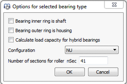
The type of cylindrical roller bearing NU, NJ, NUP … can be selected in the options dialog of the bearing.
For cylindrical roller bearings which support axial loads, a radial and axial clearance can be specified. It is important to enter a value for axial clearance if tilting occurs. For NUP type, the axial clearance has influence on the reaction moment. The Y-factor for ISO 281 life calculation is not specified in the standard, a value of Y=0.6 with e=0.2 is used like in some bearing catalogs.
For NUP type, the axial clearance is measured between left and right positions of the rings like for deep groove ball bearings. For directional bearings like NJ, the axial clearance is between reference position and one side like for angular contact ball bearings or taper roller bearings.
For types which do not support axial loads like NU, the axial displacement ‘ux’ has to be selected as input instead of ‘Fx’.
The number of sections for the calculation of load distribution can be changed in bearing options, too. The minimum is 31 sections. A larger value reduces the edge stresses by the approximation function in ISO 16281 if the extended method for pressure distribution is not active.