A symmetric stiffness matrix can be defined between the supports (only those which are connected to the housing) and the housing.
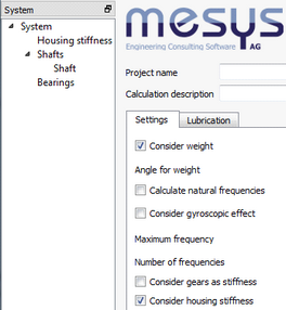
In order to make use of this option, the corresponding flag of ‘Consider housing stiffness’ must be activated at the tab-page ‘Settings’ which it is shown when selecting ‘System’ from the software tree.
The  -button, located under the matrix, can be used to create an additional stiffness matrix, which is referenced with a number shown in a box titled ‘Selected stiffness matrix’. Any one or all of these created matrices can be excluded for the calculation at any time by using the flag titled ‘Consider stiffness’. In this way, any matrix data can be kept, even though it is not being used for the analysis. In case we do want to erase any of the matrices, the
  -button can be employed for it. The entry field can be used to name them and their names will be shown in the report.
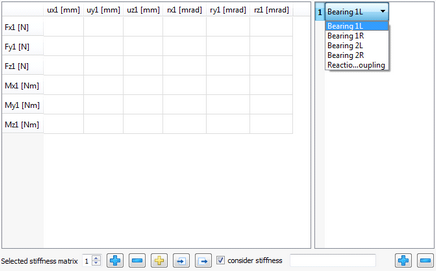
By clicking once the -button on the right lower corner, a new numbered element is listed on the window above it and a matrix is shown on a bigger window. With a double click on this element a drop-down list is shown letting us choose the support to consider. By repeating this procedure, we could add other existing bearings or supports on the list, and therefore their corresponding lines and columns of the stiffness matrix would be shown and taken into account.
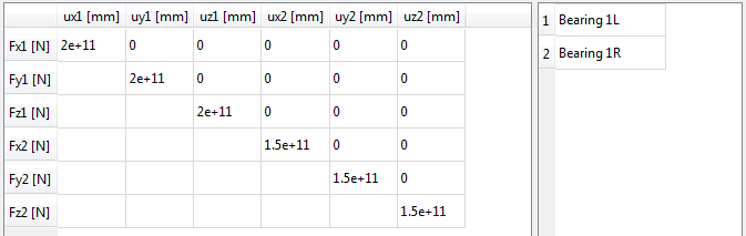
All the values for the stiffness can be entered manually with double click on the cells or also be loaded as a matrix, which is sometimes obtainable from a finite element analysis, by using the import button . Equally, a created matrix can be exported with the corresponding export button
 .
.
If we use the  -button, a pop-up window allows activating four additional options. As shown in the following picture, we can for instance omit the consideration of rotation stiffness, and activate the possibility to define for the connecting point, in any available direction required, a force or a moment with ‘Enter force/moment’, and also a certain displacement or rotation with ‘Enter displacement’.
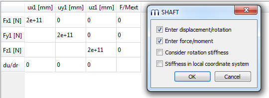
The usage of the last option lets us to consider the stiffness in the local coordinate system of the connecting point instead of the global coordinate system.