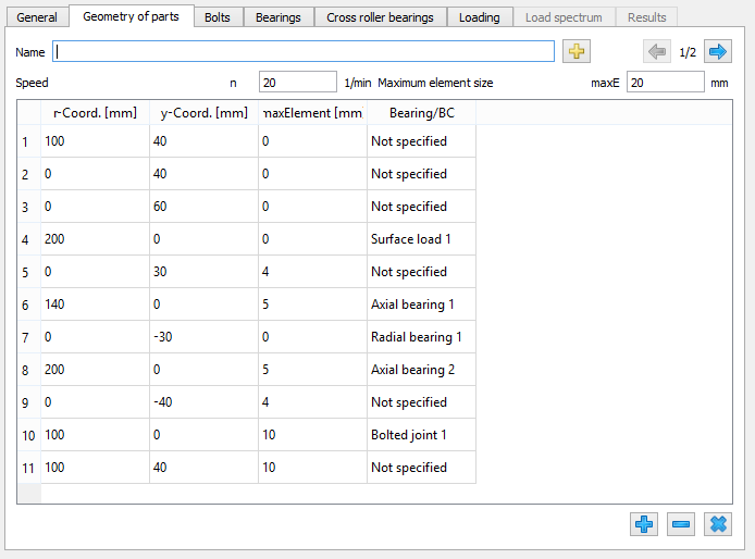
The geometry of parts is defined in a table. The points (radius and y-coordinate) have to be entered clockwise.
If the general geometry input is not activated, the geometry can be defined using horizontal and vertical lines. A coordinate which is not changed to the previous point can be set to zero. So the number of input values can be reduced by factor two.
If the general geometry input is activated, the geometry can be defined by lines in arbitrary direction. All coordinate values have to be defined in this case.
The  -button behind the name of the part allows to define the material properties for this part. The material data is only used for the FEA calculation of this part, not for the stiffness of the contact between roller and races.
Using the buttons on the lower right additional lines can be added or deleted. The  -button copies the selected line or appends a new line if nothing is selected. The
  -button deletes the selected line and the
  -button clears the whole table.