There are different view options that can be set under the tab-page ‘Settings’.
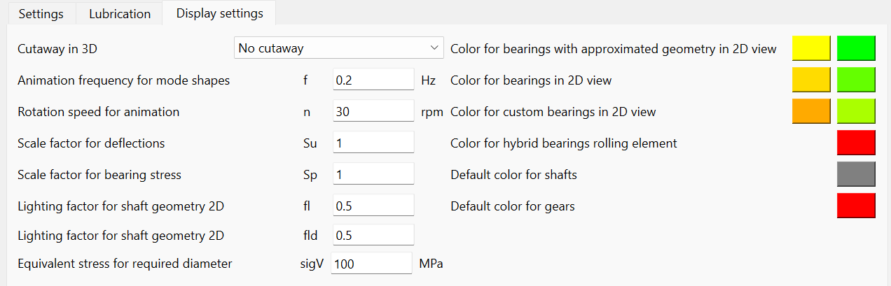
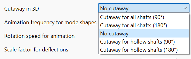
Cutaway in 3D: It is possible to generate a cutaway view for all the existing shafts. If needed, the cutaway can be only applied to the hollow shafts. This setting can be overridden for individual shafts.
With regard to the 3D animation settings, both the frequency for modes shapes and the rotation speed are adjustable. The default frequency of 0.2Hz for the mode shape above, will lead to a period of 5 seconds in the animation. The 3D pressure distribution of the bearings can be easily exaggerated with a scale factor ‘Sp’. And with the ‘Su’ the deformed shape in 3D can be also scaled. Setting 'Su' to zero will show the deformed shape in 3D without scaling, so scale factor of one.
The look of the shaft geometry in 2D can be emphasized by applying a lighting factor ‘fl’. The factor ‘fld’ is used for the shaft background graphic in 2D diagrams.
The input value for 'sigV' allows the user to specify the maximum permissible stress that any shaft shall reach under loading. In this way, the software shows graphically an approximation of required diameter of the shafts subjected to a maximum value of equivalent stress. Please refer to the ‘Graphics area’ section of this document on how to visualize the required diameter diagram.
Colors for bearings can be specified on the right of the window. The left button is for bearings, which are connected to one shaft and the housing, while the right button is for bearings connected to two shafts. The upper color is for bearings from the database with approximated internal geometry, then for bearings from the database including internal geometry and then bearings with custom geometry input.
In addition, a default color for shafts and gears can be defined.