 The load can be defined by entering geometry data for a cylindrical gear and a torque.
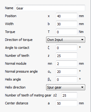
The direction of torque can either be defined by its sign or by the selection “Shaft is driven”/"Shaft is driving”. The contact point is given by an angle of contact, which is zero on the y-axis and 90° on the z-axis.
The gear is defined by the usual data on a gear drawing: Number of teeth, normal module, normal pressure angle, helix angle with its direction. Optional inputs are the number of teeth for the mating gear and the center distance. If they are given, the loads are calculated for the operating center distance, which is more accurate than on the reference diameter.
For internal gears the number of teeth has to be entered as negative value, the center distance is always positive as defined in ISO 21771 for gear geometry.
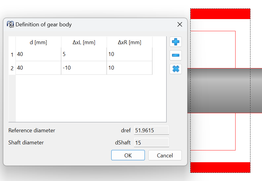
Optionally a gear body can be defined for external gears. The gear body information can be defined using an axial position for the left and right width of the gear body over the diameter. The first points are mapped down to the shaft diameter. The last points are connected to the root diameter of the gear. Internally the gear body is saved as factors to shaft and gear diameters and the gear facewidth. So if the gear data is changed, also the gear body will change. The gear body is only considered if the option Consider gears as stiffness is set to consider elastic gear bodies.