Loads can be defined on the page “Loading” for each shaft. Loads may be defined outside a shaft; masses may not be outside of a shaft. Loads can also be changed by double-clicking them in the graphics. They can be moved in the graphic by using Shift and the left mouse button.
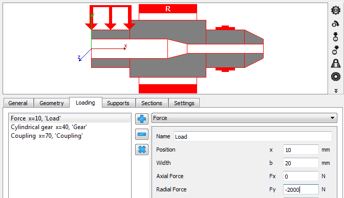
Loads can be added by the plus button next to the list. The type of the loading can be selected using the list on the right. Each load element has a name to identify it, a position relative to the left end of the shaft and a width.
The graphical representation just shows a symbol for the load, not the actual direction, as it can have six components. The coordinate system is shown on the left. The shaft axis is in x-direction, the y-axis goes up and the z-axis to the front. The weight is in negative y-directions a default (angle βw = -90°).