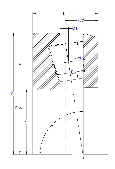
The inputs which define a tapered roller thrust bearing are a bit simpler than for the radial case of tapered roller bearings, since the distance between center of bearing and center of roller ‘δCR’ is directly entered by the user. The clearance is also defined as axial clearance.
As shown in the picture, a contact angle ranging from 90° to 0° can be set, but it should always be between 90° and 45° in order to suit its axial load-carrying design.
No radial forces can be accommodated, so the radial displacements ‘uy’ and ‘uz’ under loading have to be set to zero.
The direction of contact angle can be defined using the  -button behind contact angle or bearing type.
The height of the shoulder of the inner diameter can be defined through the factor ‘fSi’ (%) in terms of percentage of the roller diameter. The force is assumed to be located at the medium height of the shoulder.
No tolerances are considered for axial tapered roller bearings.