A 3D elastic part as housing can be connected to shafts in different groups, it does not rotate and at least one face has to be set as fixed. Currently, it can only be imported from CAD geometry as STEP file or as Nastran mesh.
Using the  -button behind “Import CAD geometry” a STEP file can be selected. An assembly with connected parts is glued together automatically. Afterwards the required mesh size can be entered. Alternatively, a Nastran mesh can be imported; only the surface mesh is kept in this case.
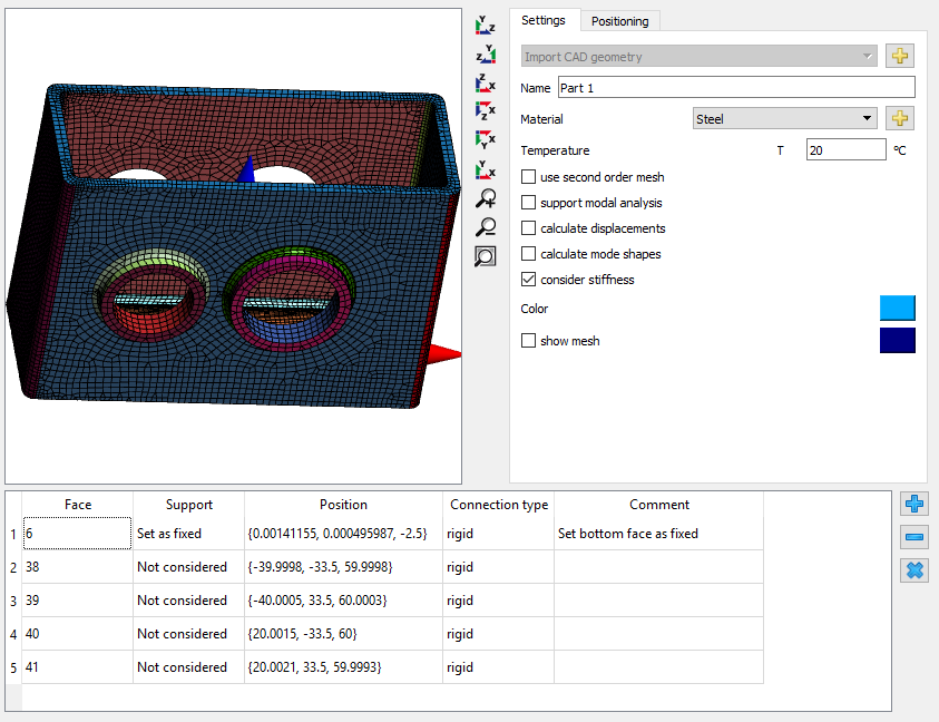
In the 3D view for the parts now multiple faces can be selected by mouse double click on a face. The faces can then be connected to a shaft support element or “Set as fixed”. As above a rigid connection or an averaged connection can be selected. To merge two connected faces, select both faces in the table, press the right mouse button and select “Merge faces”. If faces are inside the part a clipping of front faces can be activated using the context menu in the 3D-view. Using Alt-Button and left mouse button the clip-plane can be moved.
Under settings as before the material and options for a second order (quadratic) mesh and for calculation of the displacements can be selected. In addition, a 3D elastic housing can be supported in modal analysis; if “calculate mode shapes” is selected, the mode shapes can be shown, too. Under “Positioning” the position and rotation of the 3D part can be defined.
The selected support element will be connected to the nodes of the selected faces. A rigid or averaged connection will be considered, no contact and no clearance will be considered.