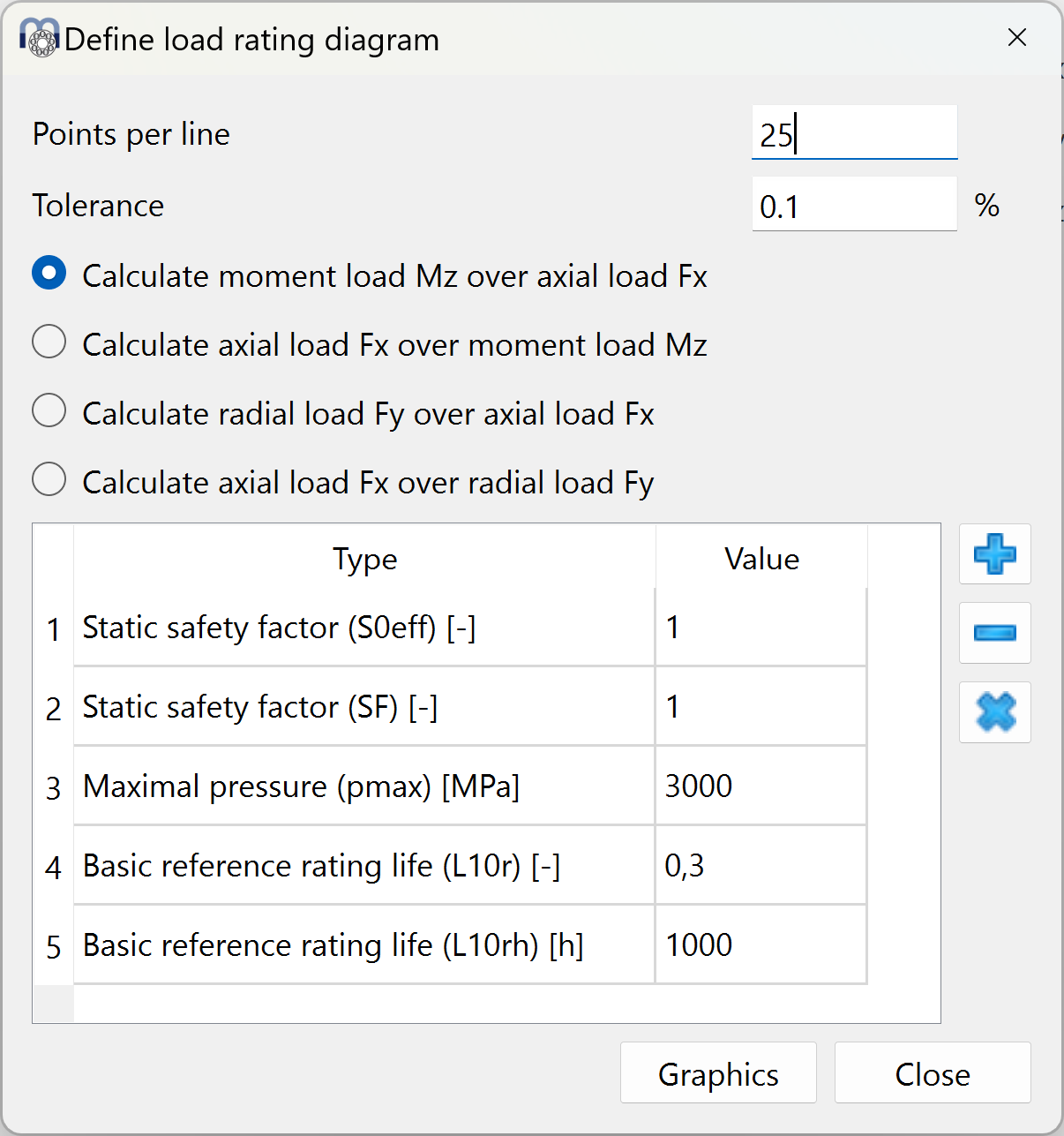
A load rating diagram can be configured at menu ‘Calculation’->’Load rating diagram’. It allow us to show four possible line charts, where the variables of the XY axes are compared against each other (Mz-Fx, Fx-Mz, Fy-Fx, Fx-Fy) while maintaining constant five types of values predefined by the user (see the picture). These diagrams are often used for slewing rings.
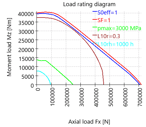
In the following picture it is shown a graphic example of the load rating diagram by which tilting moment (Mz) is compared against axial load (Fx) for a safety factor of 1, maximal pressure of 3000 MPa, 300.000 cycles and 1000 h.
For each axial load, the tilting moment is increased until the selected criteria are reached. The number of points used for one line and a tolerance for the calculation can be defined.