By right-clicking the main graphics area in 2D mode, a context menu called ‘Diagram’ offers the possibility of overlaying some shaft-related diagrams on the actual geometry of the shaft.
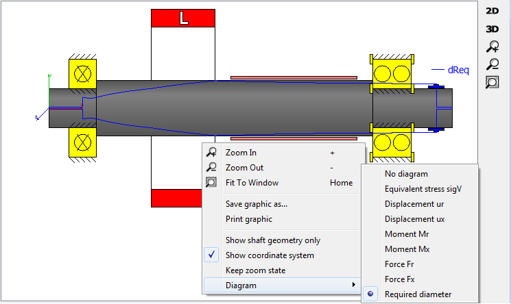
An additional diagram called ‘Required diameter’ can be overlaid to the 2D geometry of the shaft. It provides a clue as to how the size of the diameter should be in order not to exceed a maximum equivalent stress value (see the image above), which is defined under the tab-page ‘Display settings’.