If multiple groups are defined, a page for gear connections is shown. Gear connections can be added using the  -button. The shafts and gears in contact can be defined and the basic data for the gear pair is shown. The data for the gears can be modified in this window in addition to the inputs at the single shaft but using the connection allows to change data for both gears at the same time.
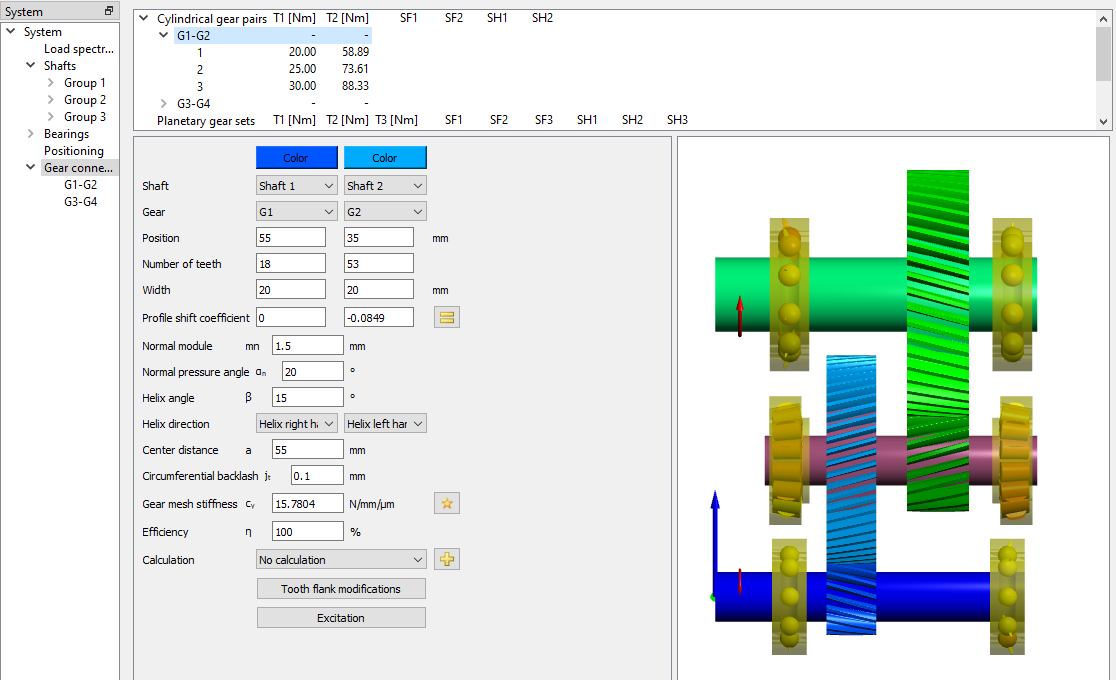
The torque on each gear pair is shown in the list at the top; the safety factors are shown if a connection to a gear calculation program is set up.
With a click on the items for the gear pairs in the system tree on the left the gear calculation program can be started to define details for the gear pair. The shaft calculation is passing basic gear geometry (z, b, x, mn, αn, β, x, a) and loading to the gear calculation; it is reading back the same geometry data and the safety factors. The colors of the gears can be changed by clicking on the “Color” button shown in the picture.
If a gear is considered in a connection, its torque input is hidden at the corresponding input window under the page ‘Loading’.