If this setting is activated, a gyroscopic matrix is considered in the calculation of natural frequencies. The mass inertia around x-axis and the speed of the shaft are required for this gyroscopic matrix.
The  -button allows some additional inputs for the Campbell diagram:
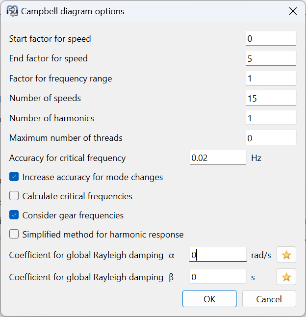
•The diagram is generated for speeds between start and end factor times the current input value for speed.
•The factor for frequency range defines the length of the ordinate of the Campbell diagram. More frequencies are calculated for a given speed range in case of a larger factor.
•The number of speeds is the number of calculation points. Reduce it for faster calculation. For harmonic response over speed a larger value leads to smoother curves.
•The number of harmonics shows additional lines for multiples of shaft speed.
•The Campbell diagram is calculated in parallel as default. The maximum number of threads can be used to limit the number of threads that are used. This can be applicable if the system memory is not sufficient for multiple parallel calculations of large systems.
•The accuracy for critical frequency is a tolerance for calculation of critical speeds as intersections of shaft speed and natural frequency.
•If ‘Increase accuracy for mode changes’ is selected, additional points are calculated when an axial mode changed into a radial mode for example.
•If ‘Calculate critical frequencies’ is selected, the critical frequencies are calculated when the Campbell diagram is shown. Else they are only calculated for the report of critical speeds. The diagram harmonic response over speed gets more accurate in this option is set because additional calculation points at the critical speeds are considered.
•If ‘Consider gear frequencies’ is selected, additional lines for gear tooth frequencies are shown and the corresponding critical frequencies are calculated.
•If the simplified method for harmonic response is activated, the harmonic response is calculated as superposition of mode shapes. The accuracy of the solutions depends of the calculated number of mode shapes in this case. For large systems the calculation can be faster if the option is activated. The result is more accurate if it is not activated.
•Coefficients for global Rayleigh damping are used to define a global damping matrix as D=α*M+β*K using the global mass matrix M and the global stiffness matrix K. Using the sizing button, the values can be calculated so that a user defined damping ratio will result for two given frequencies.